9
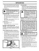
• When you have completed your turn-around, release
the drive control bar and lower handle. Place shift
lever in till position and move throttle control to de sired
speed. To begin tilling, hold drive control bar against
the handle.
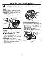
TO TRANSPORT
CAUTION: Before lifting or trans port ing,
allow tiller engine and muffler to cool.
Disconnect spark plug wire. Drain
gasoline from fuel tank.
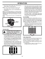
AROUND THE YARD
• Release the depth stake pin. Move the depth stake
down to the top hole for transporting the tiller. Place
depth stake pin in hole of depth stake to lock in posi-
tion. This prevents tines from scuffing the ground.
• Place shift lever indicator in “F” (forward) position for
transporting.
• Hold the drive control bar against the handle to start
tiller movement. Tines will not turn.
• Move throttle control to desired speed.
AROUND TOWN
• Disconnect spark plug wire.
• Drain fuel tank.
• Transport in upright position to prevent oil leakage.
OPERATION
e
ng
i
n
e_a
rt_
4
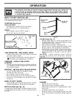
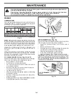
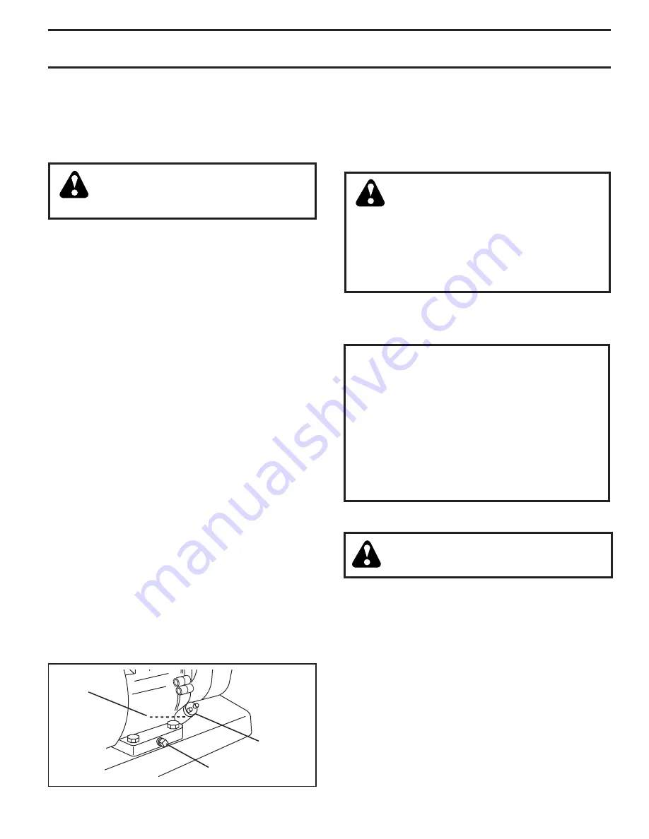
OIL
LEVEL
OIL DRAIN
PLUG
OIL
FILLER
PLUG
Fig. 12
BEFORE STARTING ENGINE
IMPORTANT
: BE VERY CAREFUL NOT TO ALLOW DIRT
TO ENTER THE ENGINE WHEN CHECKING OR ADDING
OIL OR FUEL. USE CLEAN OIL AND FUEL AND STORE IN
AP PROVED, CLEAN, COVERED CONTAINERS. USE CLEAN
FILL FUNNELS.
CHECK ENGINE OIL LEVEL (See Fig.12)
•
The engine in your unit has been shipped, from the
factory, already filled with SAE 30 summer weight oil.
•
With engine level, clean area around oil filler plug and
remove plug.
•
Engine oil should be to point of overflowing when engine
is level. For ap proxi mate capacity see “PROD UCT
SPEC I FI CA TIONS” on page 3 of this manual. All oil
must meet A.P.I. Service Classification SG-SL.
• For cold weather operation you should change oil for
easier starting (See oil viscosity chart in the Mainte-
nance sec tion of this manual).
• To change engine oil, see the Maintenance section in
this manual.
TO START ENGINE (See Fig. 13)
CAUTION: Keep drive control bar in
“DISENGAGED” position when start-
ing en gine.
When starting engine for the first time or if engine has run
out of fuel, it will take extra pulls of the recoil starter to
move fuel from the tank to the engine.
• Make sure spark plug wire is prop er ly connected.
• Move shift lever indicator to “N” (neutral) position.
• Place throttle control in “FAST” position.
• Turn fuel shut-off valve 1/4 turn to open position.
• Move choke control to choke position.
• Grasp recoil starter handle with one hand and grasp
tiller handle with other hand. Pull rope out slowly until
engine reaches start of com pres sion cycle (rope will
pull slightly harder at this point).
• Pull recoil starter handle quickly. Do not let starter
handle snap back against starter.
• If engine fires but does not start, move choke control
to half choke position. Pull recoil starter handle until
engine starts.
ADD GASOLINE
• Fill fuel tank to bottom of filler neck. Do not overfill.
Use fresh, clean, regular un lead ed gasoline with a
minimum of 87 octane. (Use of leaded gasoline will
increase carbon and lead oxide deposits and reduce
valve life). Do not mix oil with gasoline. Purchase fuel
in quan ti ties that can be used within 30 days to assure
fuel freshness.
CAUTION: Fill to within 1/2 inch of top
of fuel tank to prevent spills and to allow
for fuel expansion. If gasoline is ac-
ci den tal ly spilled, move machine away
from area of spill. Avoid creating any
source of ignition until gasoline vapors
have disappeared.
Wipe off any spilled oil or fuel. Do not
store, spill or use gasoline near an
open flame.
IMPORTANT:
WHEN OPERATING IN TEMPERATURES
BELOW32°F(0°C), USE FRESH, CLEAN WINTER GRADE
GAS O LINE TO HELP INSURE GOOD COLD WEATHER
START ING.
CAUTION: Alcohol blended fuels (called
gas o hol or using ethanol or methanol) can at-
tract moisture which leads to sep a ra tion and
for ma tion of acids during storage. Acidic gas
can damage the fuel system of an engine while
in storage. To avoid engine problems, the fuel
system should be emptied before stor age of
30 days or longer. Drain the gas tank, start
the engine and let it run until the fuel lines
and carburetor are empty. Use fresh fuel next
sea son. See Storage In struc tions for additional
information. Never use engine or carburetor
cleaner products in the fuel tank or permanent
damage may occur.
Summary of Contents for CRT900
Page 1: ...Owner s Manual 532 43 95 06 CRT900 ...
Page 27: ...27 SERVICE NOTES ...


