11
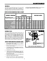
GENERAL
The warranty on this tiller/cultivator does not cover items that
have been subjected to operator abuse or negligence. To
receive full value from the warranty, the operator must main-
tain the tiller/cultivator as instructed in this manual. The follow
SERVICE DATES
SCHEDULE
Tighten All Screws and Nuts
After
first 2
Hours
Every
25
Hours
Every
75
Hours
Fill in dates as you
complete regular service
Before
Each
Use
Lubricate Transmission
Lubricate Tine Shaft
Clean and Re-Oil Air Cleaner Filter
Check Spark Plug
Cylinder Exhaust Ports
Before
Storage
SERVICE RECORDS
Drain Fuel
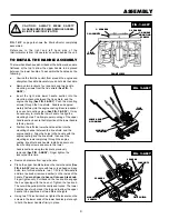
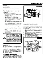
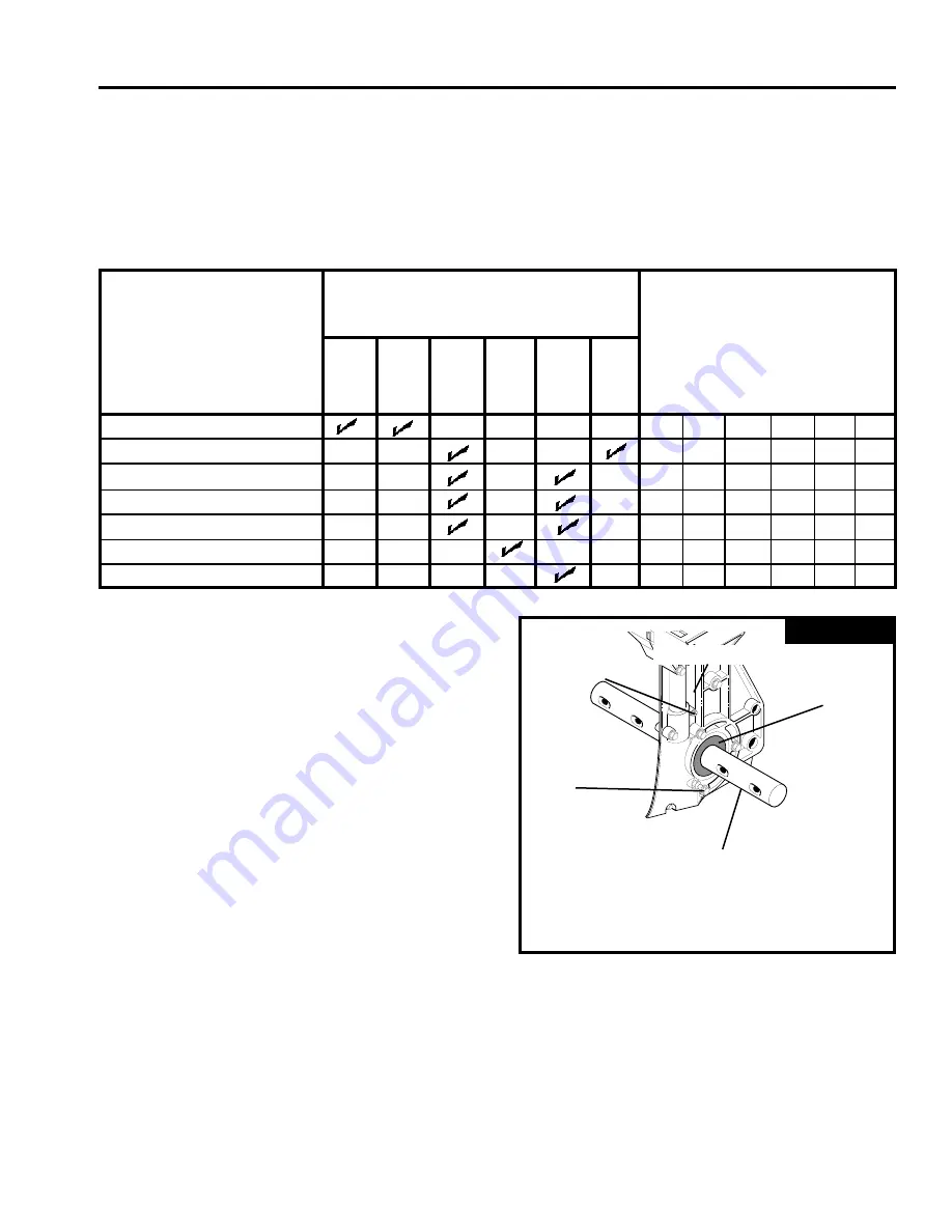
LUBRICATION
Every 25 hours and/or at the beginning of each season, the
gear box should be filled with lubricant. Tubes of gear lubricant
are available from most automotive supply stores. Use por-
table tool grease such as Lubriplate 630AA (Product No.
06787 - 1-3/4 oz. tube) or Lubriplate GR-132 (Product No.
15892 - 10 oz. tube). The tine shaft should have oil applied
before storage and after cleaning if the tiller/cultivator is
flushed with water. The following illustration is provided to
assist the operator properly maintain the tiller/cultivator.
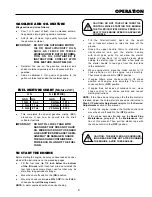
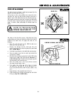
CHECK TRANSMISSION GREASE LEVEL
●
Remove both left side tines (See Service and Adjust -
ments section) in this manual.
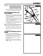
●
Remove the air vent screw (See FIG. 1-C.R.) from the top
left side of the transmission.
●
Using a grease gun, fill the transmission through the
grease fitting until the new grease begins to come out of
the air vent screw hole.
●
Reinstall the air vent screw.
●
Check the condition of the felt washer in the side of the
transmission at the tine shaft (See FIG. 1-C.R.). Re
place the felt washer if it is damaged (See Repair Parts
section in this manual).
●
Clean tine shaft, spread a few drops of oil on shaft in tine
replacement areas. Reinstall the tines.
●
Remove the right side tines. Check the felt washer for
damage, clean and oil the tine shaft. Reinstall the tines.
SERVICE RECOMMENDATIONS CHART
TINE SHAFT
(Oil the tine shaft before storage
and after cleaning if the
dethatcher/ cultivator is flushed
with water)
FELT
WASHER
TRANSMISSION
VIEW OF LEFT SIDE WITH TINES REMOVED
ing Service Recommendations Chart is provided to assist
the operator properly maintain the tiller/cultivator.
FIG. 1-C.R.
Before
Each
Season
GREASE
FITTING
(Lubricate the
gear box with
Lubriplate
630AA or
Lubriplate GR-
132)
AIR VENT
SCREW
MAINTENANCE


