4
Figure 4
Figure 5
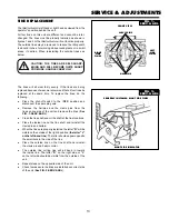
LOWER END
OF HANDLE
TINE
SHIELD
MOUNTING
CHANNEL
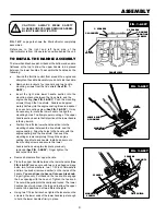
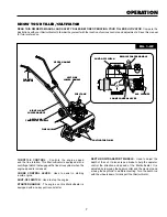
FIG. 1-OP on page 6 shows the tiller/cultivator completely
assembled.
Reference to the right and left hand side of the
tiller/cultivator is from the operator's position behind the unit.
TO INSTALL THE HANDLE ASSEMBLY
The lower handles have a short bend at the bottom end and are
flattened at the top to allow the upper handle to be placed
between the lower handles. To assemble the handles, do the
following:
●
Unwind the throttle control from around the engine and
straighten the cable. Be careful you do not kink the cable.
●
Remove two locknuts, four spacers and two handle
mounting screws from the tine shield (See FIG. 1-
ASSY).
●
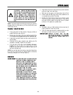
Insert the right side lower handle section into the
mounting channel between the tine shield and the
engine casting (See FIG. 2-ASSY). Push the mounting
screws through the tine shield , handle and approxi
mately halfway into the engine casting. Be sure a spacer
is on each mounting screw (See FIG. 3-ASSY). It may
be necesary to rotate the lower handle to align the
mounting holes. To allow proper mounting of the upper
handle section be sure the flat portion of the lower handle
is facing inward.
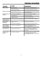
●
Position the left side lower handle section into the
mounting channel between the tine shield and the
engine casting. Align the holes in the handle with the
engine casting and the tine shield, then push the
mounting screws completely through the engine
casting, tine shield and handle. Install a spacer onto
the mounting screws and secure the lower
handle sections using two locknuts previously
removed (See FIG . 3-ASSY). Finger tighten the
locknuts at this time.
FIGURE 3
2 LOCKNUTS
2 HANDLE
MOUNTING
SCREWS
FRONT VIEW
2 SPACERS
2 SPACERS
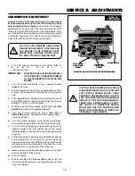
FIG. 1-ASSY
FIG. 2-ASSY
SPACERS
TINE SHIELD
LOCKNUTS
SPACERS
MOUNTING
SCREWS
CAUTION: ALWAYS WEAR SAFETY
GLASSES OR EYE SHIELDS WHILE ASSEM-
BLING TILLER/CULTIVATOR.
TINE
SHIELD
FIG. 3-ASSY
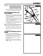
ASSEMBLY
●
Remove hardware from upper handle.
●
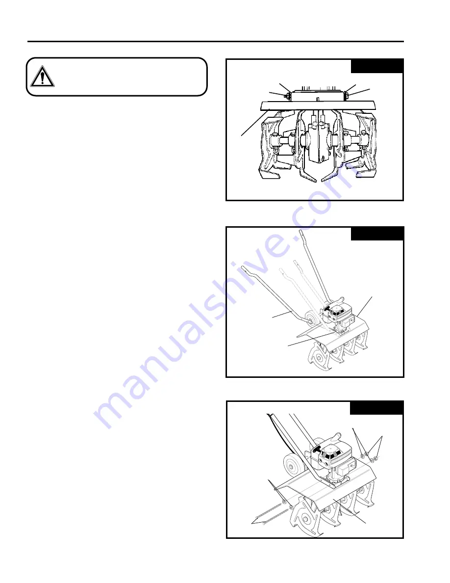
Place the upper handle between the lower handles (See
FIG. 4-ASSY) and secure with two curved head carriage
bolts, two formed washers, two 11/32 inch flatwashers
and two tee knobs (removed earlier) on the inside of the
handle. You must insert a hex nut into each tee knob.
Finger tighten only. Pull back on the tee knob to engage
the hex opening with the hex nut. Tighten the tee knob.
The nut will be pulled into the cavity and locked. The lower
handles have two holes at the top end to allow the upper
handle to be positioned at two different heights.
●
Using two 7/16 inch wrenches, tighten the locknuts on the
screws in the lower ends of the lower handles just enough
to hold the lower handles firmly in place.


