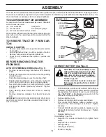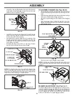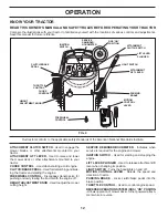
background image

20

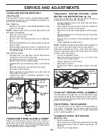
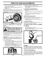
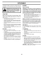
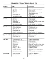
MAINTENANCE

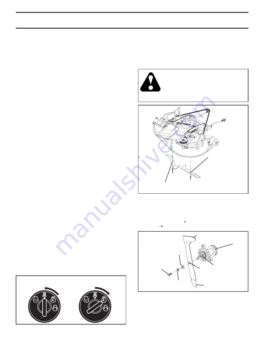
FIG.21

FIG.20

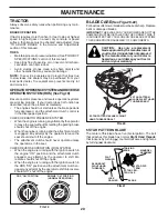
5 STAR PATTERN BLADE 

The center of this blade has a five (5) star pattern. The bolt 

that attaches this blade has nor mal 

Right Hand threads


that loosens by turn ing (


) counterclockwise and tight ens 

by turning (  ) clockwise.

BLADE CARE

(See Figs.20-22)

For best results mower blades must be kept sharp.  Replace 

bent or damaged blades.

IMPORTANT: 

THE BLADES ON YOUR MOW ER ARE NOT THE 

SAME AND MUST BE INSTALLED ON THE CORRECT SIDE. IT 

IS SUG GEST ED THAT YOU WORK ON ONE BLADE AT A TIME 

TO ENSURE PROP ER ASSEMBLY OF COMPONENTS.

RH

02

22

3

BLADE BOLT 

RIGHT HAND 

THREADED

LOCK 

WASHER

FLAT 

WASHER

BLADE

MANDREL 

ASSEMBLY

5 STAR PAT-

TERN

5 STAR CEN-

TER HOLE

TRAILING 

EDGE

6 STAR PATTERN 

BLADE W/LEFT HAND 

THREAD ED BOLT

5 STAR PATTERN BLADE W/RIGHT 

HAND THREAD ED BOLT

CAUTION:  Use only a replacement 

blade approved by the manufacturer of 

your tractor. Using a blade not approved 

by the manufacturer of your tractor is 

hazardous, could damage your tractor 

and void your warranty.

TRACTOR

Always observe safety rules when per form ing any main-

 te nance.

BRAKE OPERATION

If tractor requires more than five (5) feet to stop at highest 

speed in high est gear on a level, dry concrete or paved 

surface, then brake must be checked and ad just ed. (See 

“TO ADJUST BRAKE” in the Ser vice and Ad just ments 

section of this manual).

TIRES

• 

Maintain proper air pressure in all tires (See “PROD UCT 

SPEC I FI CA TIONS” section of this man ual).

• 

Keep tires free of gasoline, oil, or insect control chemi-

 cals which can harm rubber.

•  Avoid stumps, stones, deep ruts, sharp objects and 

other hazards that may cause tire damage.

NOTE: 

To seal tire punctures and pre vent flat tires due 

to slow leaks, tire sealant may be purchased from your 

local parts dealer. Tire sealant also pre vents tire dry rot 

and corrosion.

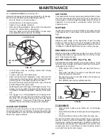
OPERATOR PRESENCE SYS TEM AND REVERSE 

OPERATION SYSTEM (ROS) (See Fig.19)

Be sure operator presence and reverse operation sys tems 

are work ing properly.  If your tractor does not function as 

described, repair the problem immediately.

•  The engine should not start unless the brake pedal is 

fully de pressed, and the attachment clutch con trol is 

in the dis en gaged position.

CHECK OPERATOR PRESENCE SYSTEM

• 

When the engine is running, any attempt by the op er a tor 

to leave the seat without first setting the parking brake 

should shut off the engine.

• 

When the engine is running and the at tach ment clutch 

is engaged, any attempt by the operator to leave the 

seat should shut off the engine.

•  The attachment clutch should never operate unless 

the operator is in the seat.

CHECK REVERSE OPERATION (ROS) SYSTEM 

•  When the engine is running with the ignition switch in 

the engine "ON" position and the at tach ment clutch 

engaged, any attempt by the operator to shift into 

reverse should shut off the engine.

•  When the engine is running with the ignition switch in 

the ROS "ON" position and the at tach ment clutch en-

gaged, any attempt by the operator to shift into reverse 

should NOT shut off the engine.

828

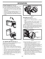
ROS "ON" POSITION

ENGINE "ON" POSITION

(NORMAL OPERATING)

FIG.19

Summary of Contents for CTH2036 TWIN

Page 1: ...CTH2036 TWIN 04040 Owner s Manual ...

Page 2: ...catcher or unclogging the discharge guard Operate machine only in daylight or good artificial light Do not operate the machine while under the influence of alcohol or drugs Watch for traffic when operating near or crossing roadways Use extra care when loading or unloading the machine into a trailer or truck Always wear eye protection when operating ma chine Data indicates that operators age 60 yea...

Page 3: ...signed for towing Do not attach towed equipment except at the hitch point Follow the manufacturer s recommendation for weight limits for towed equipment and towing on slopes Never allow children or others in or on towed equip ment On slopes the weight of the towed equipment may cause loss of traction and loss of control Travel slowly and allow extra distance to stop V SERVICE SAFE HANDLING OF GASO...

Page 4: ...n effective working order by the operator In the state of California the above is required by law Section 4442 of the California Public Resources Code Other states may have similar laws Federal laws apply on federal lands CUSTOMER RESPONSIBILITIES Read and observe the safety rules Follow a regular schedule in maintaining caring for and using your tractor Follow the instructions under the Maintenan...

Page 5: ...5 UNASSEMBLED PARTS Steering Wheel 1 Washer 1 Knob Steering Wheel Insert Seat 1 Seat Steering Wheel Adapter Keys 2 Keys Slope Sheet 1 Oil Drain Tube For Future Use 1 Large Flat Washer 1 Locknut ...

Page 6: ...smanual itmeans when you are in the operating position seated behind the steering wheel TO REMOVE TRACTOR FROM CAR TON UNPACK CARTON Remove all accessible loose parts and parts cartons from carton Cut along dashed lines on all four panels of carton Remove end panels and lay side panels flat Check for any additional loose parts or cartons and remove Your new tractor has been assembled at the factor...

Page 7: ...f this manual Be sure tractor is in a well ventilated area Be sure the area in front of tractor is clear of other people and objects TO ROLL TRACTOR OFF SKID See Op eration section for location and function of controls Press lift lever plunger and raise attachment lift lever to its highest position Release parking brake by depressing clutch brake pedal Place freewheel control in transmission disen...

Page 8: ...ate install the bagger support tube to the back plate as shown Tighten securely Install the two upper support brackets through the back plate and to the chassis install the clevis pin 10x17mm and secure with retainer spring Assemble both support brackets to the outside of the bagger support tube using two each 3 8 x 63 5mm hex bolts13 32 I D flatwashersand3 8locknutsfromparts bag Tighten securely ...

Page 9: ...en the nuts securely VERTICAL ADJUSTMENT Slightlyloosenthenutssecuringtheverticaladjustment brackets Loosen only enough so the brackets keep their position but allow them to be moved Move the brackets the amount up or down you wish the bag assembly to move Retighten the nuts securely Reinstall the bagger assembly and check the bagger to fender fit If necessary repeat the procedure until proper fit...

Page 10: ... fresh clean regular unleaded gasoline Become familiar with all controls their location and function Operate them before you start the engine Be sure brake system is in safe operating condition It is important to purge the transmission before op erating your tractor for the first time Follow proper starting and transmission purging instructions See TO START ENGINE and PURGE TRANSMISSION in the Ope...

Page 11: ... safety inform ation about hazards which can result in death serious injury and or property damage DANGER indicates a hazard which if not avoided will result in death or serious injury WARNING indicates a hazard which if not avoided could result in death or serious injury CAUTION indicates a hazard which if not avoided might result in minor or moderate injury CAUTION when used without the alert sy...

Page 12: ...ushing or slowly towing the tractor with the engine off HEIGHTADJUSTMENTKNOB Usedtoadjustthemower cutting height SERVICE REMINDER HOURMETER Indicates when service is required for the engine and mower IGNITION SWITCH Used for starting and stopping the engine LIFT LEVER PLUNGER Used to release attachment lift lever when changing its position LIGHT SWITCH Turns the headlights on and off MOTION CONTRO...

Page 13: ... cutting height Turn knob counterclockwise to lower cutting height The cutting height range is approximately 1 1 2 to 4 The heights are measured from the ground to the blade tip with the engine not running These heights are approximate and may vary depending upon soil conditions height of grass and types of grass being mowed The average lawn should be cut to approximately 2 1 2 inches during the c...

Page 14: ...tion of this manual With mower in desired height of cut position gauge wheels should be assembled so they are slightly off the ground Install gauge wheel in appropriate hole with shoulder bolt 3 8 washer and 3 8 16 locknut and tighten securely Repeatforoppositesideinstallinggaugewheelinsame adjustment hole SHOULDER BOLT LOCKNUT 3 8 WASHER REVERSE OPERATION SYSTEM ROS Your tractor is equipped with ...

Page 15: ... See Figs 9 and 14 When pushing or towing your tractor be sure to disengage transmission by placing freewheel control in freewheeling position Free wheel control is located under the seat Raiseattachmentlifttohighestpositionwithattachment lift control Raise seat and pull freewheel control up and back into the slot and release so it is held in the disengaged position Do not push or tow tractor at m...

Page 16: ...e used during the engine warm up period after the transmission has been warmed up and may require the choke control be pulled out slightly NOTE If at a high altitude above 3000 feet or in cold temperatures below 32 F the carburetor fuel mixture may need to be adjusted for best engine performance See TO ADJUST CARBURETOR in the Service and Adjustments section of this manual ADD GASOLINE Fill fuel t...

Page 17: ...give best performance of the attachment being used OPERATION Certaintypesofgrassandgrassconditionsmayrequire that an area be mulched a second time to completely hide the clippings When doing a second cut mow across perpendicular to the first cut path Change your cutting pattern from week to week Mow northtosouthoneweekthenchangetoeasttowestthe next week This will help prevent matting and graining ...

Page 18: ...lector to allow mower to operate You are now ready to begin mulching BAGGING See Fig 18 Place deck into the high cut position Remove the rear discharge deflector or mulching plug Insert the discharge chute into the opening in the backplate and onto the mower deck adaptor Attachthechutetothetractorbyhookingthetwostraps to the flange of the chute NOTE Thestraphookmustgothroughthedischargechute only ...

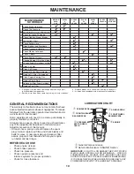
Page 19: ...n air filter assure proper air fuel mixture and help your engine run better and last longer BEFORE EACH USE Check engine oil level Check brake operation Check tire pressure Check operator presence and interlock systems for proper operation Check for loose fasteners T R A C T 0 R Inspect Muffler Spark Arrester Clean Air Filter Change Engine Oil with oil filter Replace Air Filter Paper Cartridge Rep...

Page 20: ...ual Keep tires free of gasoline oil or insect control chemi cals which can harm rubber Avoid stumps stones deep ruts sharp objects and other hazards that may cause tire damage NOTE To seal tire punctures and prevent flat tires due to slow leaks tire sealant may be purchased from your local parts dealer Tire sealant also prevents tire dry rot and corrosion OPERATORPRESENCESYSTEMANDREVERSE OPERATION...

Page 21: ...to assure proper cooling Do not attempt to clean fan or transmission while engine is running or while the transmission is hot To prevent pos sible damage to seals do not use high pressure water or steam to clean transaxle Inspect cooling fan to be sure fan blades are intact and clean Inspect cooling fins for dirt grass clippings and other materials To prevent damage to seals do not use compressed ...

Page 22: ...cap dipstick for checking level Insert dipstick into the tube and rest the oil fill cap on the tube Do not thread the cap onto the tube when taking reading Keep oil at FULL line on dipstick Tighten cap onto the tube securely when finished MUFFLER Inspect and replace corroded muffler and spark arrester if equipped as it could create a fire hazard and or dam age SPARK PLUGS Replace spark plugs at th...

Page 23: ...nto clutch pulley groove Installleftfrontlinkintothelefthandfrontmowerbracket retain with single loop retainer springs as shown Slide right side of mower back and install right front link into right hand front mower bracket retain with single loop retainer springs Placethesuspensionarmsonmowerpins ifnecessary rock and raise front of mower to align mower pins with the holes in suspension arms Retai...

Page 24: ...T E NUT F FRONT LINKS TRUNNION FRONT TO BACK ADJUSTMENT See Figs 28 and 29 IMPORTANT DECK MUST BE LEVEL SIDE TO SIDE IF THE FOLLOWINGFRONT TO BACKADJUSTMENTISNECESSARY BE SURE TO ADJUST BOTH FRONT LINKS EQUALLY SO MOWER WILL STAY LEVEL SIDE TO SIDE To obtain the best cutting results the mower housing should be adjusted so that the front is approximately 1 8 to 1 2 lower than the rear when the mowe...

Page 25: ... cover Install mower see To install mower in this section of this manual LH MANDREL COVER BELT MANDREL PULLEY IDLER PULLEY RH MANDREL COVER MANDREL PULLEY IDLER PULLEY TO CHECK BRAKE If tractor requires more than five 5 feet to stop at highest speed in highest gear on a level dry concrete or paved surface then brake must be serviced You may also check brake by 1 Park tractor on a level dry concret...

Page 26: ...creeps repeat above steps until satis fied TRANSMISSION REMOVAL REPLACEMENT Should your transmission require removal for service or replacement itshouldbepurgedafterreinstallationandbe fore operating the tractor See PURGE TRANSMISSION in the Operation section of this manual TO REPLACE MOTION DRIVE BELT See Fig 32 Park the tractor on level surface Engage parking brake For assistance there is a belt...

Page 27: ...tand in front of tractor Grasp hood at sides tilt toward engine and lift off of tractor To replace reverse above procedure ENGINE TO ADJUST THROTTLE CONTROL CABLE The throttle control has been preset at the factory and adjustment should not be necessary If adjustment is necessary see engine manual TO ADJUST CARBURETOR Thecarburetorhasbeenpresetatthefactoryandadjustment should not be necessary Howe...

Page 28: ...SENTIALFUELSYSTEMPARTSSUCH AS CARBURETOR FUEL FILTER FUEL HOSE OR TANK DURING STORAGE ALSO EXPERIENCE INDICATES THAT ALCOHOL BLENDED FUELS CALLED GASOHOL OR USING ETHANOLORMETHANOL CANATTRACTMOISTUREWHICH LEADSTOSEPARATIONANDFORMATIONOFACIDSDURING STORAGE ACIDIC GAS CAN DAMAGE THE FUEL SYSTEM OF AN ENGINE WHILE IN STORAGE Empty the fuel tank by starting the engine and let it run until the fuel lin...

Page 29: ...ignition switch 7 Check replace ignition switch 8 Faulty solenoid or starter 8 Check replace solenoid or starter 9 Faulty operator presence switch es 9 Contact an authorized service center department Engine clicks but will not 1 Weak or dead battery 1 Recharge or replace battery start 2 Corroded battery terminals 2 Clean battery terminals 3 Loose or damaged wiring 3 Check all wiring 4 Faulty solen...

Page 30: ... of mower housing 8 Mower drive belt worn 8 Replace mower drive belt 9 Blades improperly installed 9 Reinstall blades sharp edge down 10 Improper blades used 10 Replace with blades listed in this manual 11 Clogged mower deck vent holes from buildup of 11 Clean around mandrels to open vent holes grass leaves and trash around mandrels Headlight s not working 1 Light switch is OFF 1 Turn light switch...

Page 31: ...ACK BLACK BLACK BLACK BLACK BLACK BLACK BLACK BLACK BLACK BLACK BLACK ELECTRIC CLUTCH 28 VOLTS AC 3600 RPM REGULATOR DISCONNECTED CHARGING SYSTEM OUTPUT 15 AMP DC 3600 RPM NON REMOVABLE CONNECTIONS REMOVABLE CONNECTIONS WIRING INSULATED CLIPS NOTE IF WIRING INSULATED CLIPS WERE REMOVED FOR SERVICING OF UNIT THEY SHOULD BE REPLACED TO PROPERLY SECURE YOUR WIRING PTO SWITCH CIRCUIT POSITION OFF C F ...

Page 32: ...32 REPAIR PARTS TRACTOR MODEL NO CTH2036TWIN 96061021700 PRODUCT NO 960 61 02 17 ELECTRICAL 33 30 28 26 24 42 43 25 41 27 27 27 40 50 197434 29 94 93 92 34 58 2 1 27 81 66 59 16 46 46 48 22 21 101 16 ...

Page 33: ...itch Seat 30 532 19 33 50 Switch Ignition 33 532 14 04 01 Key Ign Molded 34 532 11 07 12 Switch Light 40 532 19 74 34 Harness Ign 41 871 11 04 08 Bolt Flk Fin Hex 1 4 20 unc x 1 2 42 532 13 15 63 Cover Terminal Red 43 532 19 25 07 Solenoid 46 532 40 17 63 Gauge Hourmeter 48 532 14 08 44 Adapter Ammeter Rectangular 50 532 17 46 51 Switch PTO 58 532 16 94 19 Buzzer Crd 59 532 18 03 79 Switch FBI CRD...

Page 34: ...5 185 179 209 209 155 209 209 154 13 26 25 24 24 209 209 6 209 31 30 89 209 145 37 37 256 205 205 26 69 186 187 266 265 189 189 171 172 173 190 190 171 198 chassis tex_62_Tex GT Husq_CRD 3 39 278 16 9 216 18 64 15 165 17 278 278 272 273 295 300 263 28 264 301 302 303 214 213 258 259 58 278 278 35 10 33 188 188 187 26 26 25 25 209 209 207 209 207 38 216 5 8 8 1 34 170 11 184 ...

Page 35: ...Bracket Exten Chassis Rh CRD 164 532 16 56 05 Support Battery CRD 165 532 18 11 00 Cover Battery 170 532 19 94 88 Backplate CRD KEY PART NO NO DESCRIPTION NOTE All component dimensions given in U S inches 1 inch 25 4 mm KEY PART NO NO DESCRIPTION 171 872 14 06 20 Bolt Rdhd Sqnk 3 8 16 x 2 1 2 Gr 5 172 819 13 20 16 Washer 13 32 x 1 1 4 x 16 Ga 173 873 51 06 00 Nut Keps Hex 3 8 16 unc 175 532 18 82 ...

Page 36: ...9 259 187 183 156 165 82 168 166 163 14 159 161 207 158 171 112 21 8 10 167 83 162 29 28 53 36 35 27 252 35 62 36 55 258 258 27 215 37 22 34 24 96 25 252 19 263 30 16 169 171 30 263 36 255 255 35 35 36 214 163 186 207 14 65 43 9 17 261 51 120 295 262 292 266 20 199 52 199 51 199 197 16 81 16 199 84 16 185 172 95 96 263 71 200 73 16 263 63 57 183 183 183 183 180 38 47 drive hydro_CRD_Laser_20 243 2...

Page 37: ...2 12 17 48 Washer 25 32 x 1 5 8 x 16 Ga 81 532 17 00 06 Asm Shaft Cross Rear 82 532 16 57 11 Spring Torsion KEY PART NO NO DESCRIPTION KEY PART NO NO DESCRIPTION 83 819 17 12 16 Washer 17 32 x 3 4 x 16 Ga 84 532 17 00 07 Link Transaxle 95 532 17 00 15 Control Asm Bypass Hydro 96 532 12 47 88 Spring Retainer 1 112 819 09 12 10 Washer 9 32 x 3 4 x 10 Ga 120 873 90 06 00 Nut Lock Flg 3 8 16 unc 150 5...

Page 38: ...ODEL NO CTH2036TWIN 96061021700 PRODUCT NO 960 61 02 17 STEERING ASSEMBLY 5 5 4 3 43 95 43 8 10 40 11 8 6 87 46 46 8 6 87 29 88 71 17 43 91 2 33 35 34 68 67 67 67 13 65 68 15 29 29 82 38 12 39 1 41 37 36 37 steering_pl lt_70 32 ...

Page 39: ...her 11 32 x 3 4 x 16 Ga 34 810 04 05 00 Washer Lock Hvy Hlcl Spr 5 16 35 873 54 05 00 Crownlock Nut 5 16 24 unf 3847 36 532 15 51 05 Bushing Steering 37 532 15 29 27 Screw TT I0 32 x 5 x 3 8 Flange 38 532 19 36 52 Cap Wheel Steering 39 819 18 38 12 Washer 9 16ID x 2 3 8 OD x 12 Ga 40 873 54 06 00 Nut Lock 3 8 24 41 532 18 67 37 Adaptor Steering Wheel 43 532 12 17 49 Washer 25 32 x 1 1 4 x 16 Ga 46...

Page 40: ...EPAIR PARTS TRACTOR MODEL NO CTH2036TWIN 96061021700 PRODUCT NO 960 61 02 17 ENGINE 2 1 OPTIONAL EQUIPMENT Spark Arrester 29 8 10 6 5 72 13 4 25 81 3 17 14 38 23 45 engine ko twin_19_A 44 46 32 31 33 37 33 ...

Page 41: ...Shield Browning Debris Guard 25 532 18 95 41 Choke Control 29 532 13 71 80 Arrestor Spark 31 532 40 74 89 Tank Fuel 32 532 19 77 25 Cap Asm Fuel Top 33 532 12 34 87 Clamp Hose Blk 37 532 13 70 40 Line Fuel 20 38 532 18 16 54 Plug Drain Oil Easy 44 817 67 04 12 Screw Hexwsh Thdrol 1 4 20 x 3 4 45 817 00 06 12 Screw Hexwsh Thdr 3 8 16 x 3 4 46 819 09 14 16 Washer 9 32 x 7 8 x 16ga 72 532 19 23 34 Sc...

Page 42: ... 3 8 16 x 1 1 2 9 819 13 16 14 Washer 13 32 x 1 x 14 Ga 10 532 19 55 30 Pan Pnt Seat 11 532 16 63 69 Knob Seat Adj Wingnut 12 532 17 46 48 Bracket Pnt Mounting Switch KEY PART NO NO DESCRIPTION 13 532 12 12 48 Bushing Snap Blk Nyl 50 Id 14 872 05 04 12 Bolt Rdhd Sht Nk 1 4 20 x 1 1 2 15 532 12 12 49 Spacer Split 16 532 12 37 40 Spring Cprsn Plate 17 532 12 39 76 Nut Lock 1 4 Lge Flg Gr 5 Zinc 21 5...

Page 43: ... 14 08 37 Decal Saddle Brake Parking 21 532 16 62 86 Decal Deck Sch 92 CRD 532 18 19 16 Pad Footrest LH 532 18 19 17 Pad Footrest RH 532 16 69 60 Decal Bypass 532 41 02 43 Manual Owner s English KEY PART NO NO DESCRIPTION KEY PART NO NO DESCRIPTION 1 532 05 91 92 Cap Value Tire 2 532 06 51 39 Stem Value 3 532 10 62 22 Tire F Ts 15 x 6 0 6 Service 4 532 05 99 04 Tube Inner Front 35060 5 532 13 83 3...

Page 44: ...24 131 36 22 13 2 11 8 20 16 69 14 15 2 18 46 46 45 9 41 130 1 19 5 6 3 46 44 33 32 30 30 28 31 21 25 21 31 32 33 30 30 30 2 18 17 27 55 124 40 41 36 26 23 124 36 84 41 40 56 61 24 21 21 21 4 21 10 68 32 36 36 32 36 36 92cm _deck elect CRD 2 34 21 117 119 116 118 2 21 21 35 118 117 116 119 ...

Page 45: ... RF 92 CRD 26 532 40 01 10 Brace Susp Frt CRD 27 532 16 55 68 Bracket Asm Susp RR 92 CRD 28 532 16 55 67 Bracket Asm Susp LR 92 CRD 30 532 17 39 84 Screw Thd Rolling 31 532 18 76 90 Washer Spacer Mower Vented 32 532 17 57 07 Mandrel Pulleys 33 532 40 02 34 Nut Flg Top Lock 34 532 40 01 07 Bracket Gauge Wheel Lf 92 CRD 35 532 40 01 06 Bracket Gauge Wheel Rf 92 CRD 36 532 14 67 63 Pulley Idler V Gro...

Page 46: ...Nut Jam Hex 1 2 13 unc 17 532 17 56 89 Trunnion 18 873 80 08 00 Nut Lock W Wsh 1 2 13 unc 19 532 13 98 68 Arm Suspension Mower 20 532 19 42 09 Pin Cotter 7 16 Bow Tie Lock 23 532 11 08 07 Nut Special 24 819 13 10 16 Washer 13 32 x 5 8 x 16 Ga NOTE All component dimensions given in U S inches 1 inch 25 4 mm KEY PART NO NO DESCRIPTION 25 532 16 40 24 Spring 2 1 8 26 532 16 94 84 Retainer Clip 27 532...

Page 47: ...k Flg 3 8 16 UNC 15 532 12 46 70 Retainer Spring 17 872 14 05 06 Bolt Rdhd 5 16 18 unc x 3 4 19 873 90 05 00 Nut Lock Hexflange 5 16 18 20 532 18 88 47 Bracket Pivot Rh 21 532 40 61 80 Bag Asm CRD 22 532 16 57 81 Bracket Side Bagger CRD 24 532 16 57 83 Tube Pivot Bagger CRD 25 532 19 37 05 Tube Front Bagger CRD 28 532 16 57 87 Grip Handle Black 31 532 16 94 84 Retainer Clip 32 532 12 68 75 Rivet R...

Page 48: ...48 SERVICE NOTES ...

Page 49: ...49 SERVICE NOTES ...

Page 50: ...50 SERVICE NOTES ...

Page 51: ... never across the face Do not mow slopes greater than 15 degrees Make turns gradually to prevent tipping or loss of control Exercise extreme caution when changing direction on slopes 1 Fold this page along dotted line indicated above 2 Hold page before you so that its left edge is vertically parallel to a tree trunk or other upright structure 3 Sight across the fold in the direction of hill slope ...

Page 52: ...532 41 02 43 Rev 1 02 06 07 TB Printed in U S A ...

Reviews: