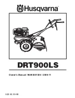
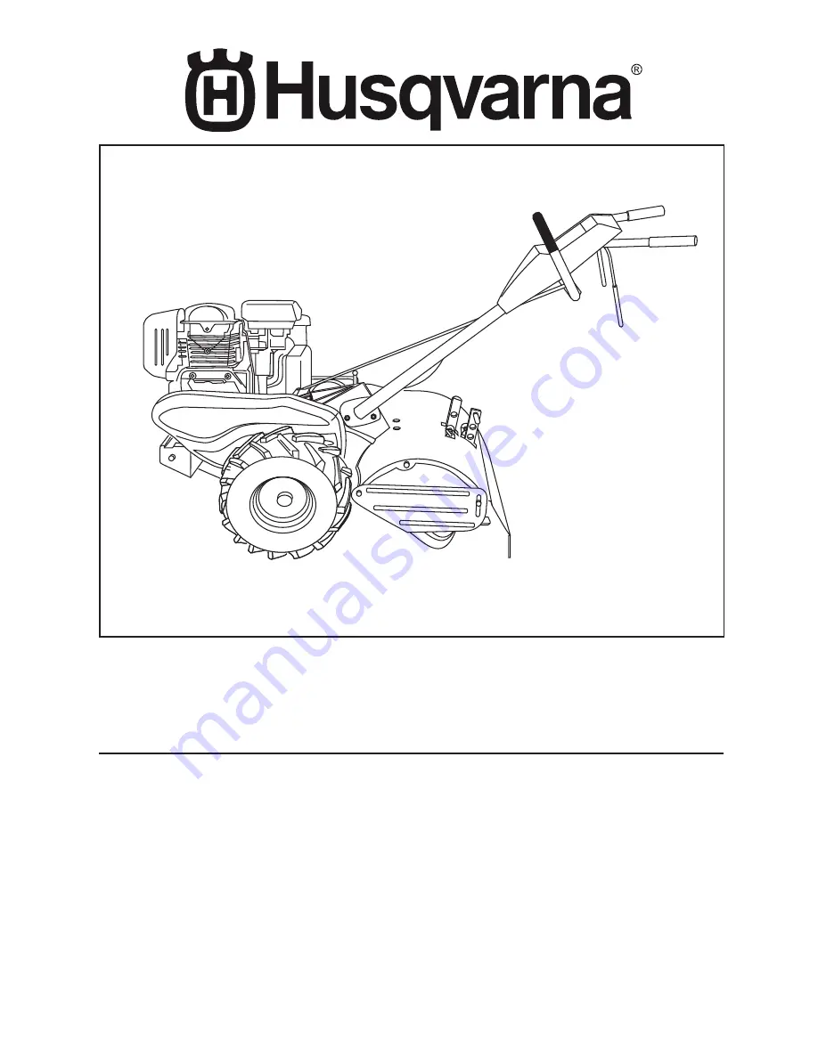
background image

Owner's Manual

 / 96093001500 / 2009-11

DRT900LS

532 43 20-90

Summary of Contents for DRT900LS

Page 1: ...Owner s Manual 96093001500 2009 11 DRT900LS 532 43 20 90 ...

Page 2: ...stop the unit and disengage the controls quickly Never allow children to operate the equipment Never allow adults to operate the equipment without proper instruction Keep the area of operation clear of all persons par ticularly small children and pets PREPARATION Thoroughly inspect the area where the equipment is to be used and remove all foreign objects Disengage all clutches and shift into neutr...

Page 3: ...uld not be used on or near any unim proved forest covered brush covered or grass covered land unless the engine s exhaust system is equipped with a spark arrester meeting applicable local or state laws if any If a spark arrester is used it should be maintained in effective working order by the operator In the state of California the above is required by law Section 4442 of the California Public Re...

Page 4: ... been assembled at the factory with exception of those parts left unassembled for shipping purposes To ensure safe and proper operation of your tiller all parts and hardware you assemble must be tightened securely Use the correct tools as necessary to insure proper tightness FRONT OPERATOR S POSITION LEFT RIGHT Fig 1 1 Hairpin Clip 1 Carriage Bolt 3 8 16 UNC x 1 Grade 5 1 Center Locknut 3 8 16 UNC...

Page 5: ... is lowered into position HANDLE ASSEMBLY Fig 3 HANDLE ASSEMBLY GEARCASE NOTCH HANDLE LOCK VIEWED FROM R H SIDE OF TILLER LOOSEN HANDLE LOCK LEVER TO MOVE TIGHTEN HANDLE LOCK LEVER TO HOLD handles_34 CARRIAGE BOLT SLOT GEARCASE HANDLE LOCK FLAT WASHER HANDLE LOCK LEVER PIVOT BOLT LOCKNUT HANDLE BASE Fig 5 Rotate handle assembly down Insert rear carriage bolt first with bolt head on L H side of til...

Page 6: ...clip through hole of shift rod to secure Fig 7 Fig 6 END OF CLUTCH CABLE CONTROL BAR CONTROL BAR BRACKET CONTROL BAR BRACKET CLUTCH CABLE ATTACH CLUTCH CABLE See Fig 6 Hook end of clutch cable through hole in control bar bracket CHECK TIRE PRESSURE The tires on your unit were overinflated at the factory for shipping purposes Correct and equal tire pressure is important for best tilling performance...

Page 7: ...safety standards of the American National Standards Institute CHOKE CONTROL Used when starting a cold engine THROTTLE CONTROL Controls engine speed DEPTH STAKE Controls depth at which tiller will dig DRAG STAKE Controls forward speed in forward rotating till position DRIVE CONTROL BAR Used to engage tines LEVELING SHIELD Levels tilled soil OUTER SIDE SHIELD Adjustable to protect small plants from ...

Page 8: ...ore versatile tilling and cultivating or to more easily transport your tiller Fig 9 depth_stake_2 TILLING See Fig 12 Release depth stake pin Pull the depth stake up for increased tilling depth Place depth stake pin in hole of depth stake to lock in position Place shift lever indicator in counter rotating till position Hold the drive control bar against the handle to start tilling movement Tines an...

Page 9: ...oil for easier starting See oil viscosity chart in the Mainte nance section of this manual To change engine oil see the Maintenance section in this manual TURNING Release the drive control bar Move throttle control to SLOW position Placeshiftleverindicatorin F forward position Tines will not turn Lift handle to raise tines out of ground Swing the handle in the opposite direction you wish to turn b...

Page 10: ... IMPORTANT WHEN OPERATING IN TEMPERATURES BELOW32 F 0 C USE FRESH CLEAN WINTER GRADE GASOLINE TO HELP INSURE GOOD COLD WEATHER STARTING CAUTION Alcohol blended fuels called gasohol or using ethanol or methanol can at tract moisture which leads to separation and formation of acids during storage Acidic gas can damage the fuel system of an engine while in storage To avoid engine problems the fuel sy...

Page 11: ...d in rough condition promoting no further growth of weeds and grass See Fig 16 Do not lean on handle this takes weight off the wheels reduces traction and may cause the tiller to skip over the ground Alwayslowerthedragstakewhenusingtheforward rotating tine drive tire_1 HAIRPIN CLIP Fig 17 OUTER VIEW OF TIRE tire_2 Fig 18 INNER VIEW OF TIRE CLEVIS PIN HAIRPIN CLIP ADJUST WHEELS FOR CULTIVATING See ...

Page 12: ...el Check tine operation Check for loose fasteners LUBRICATION Keep unit well lubricated See LUBRICATION CHART LUBRICATION CHART MAINTENANCE SCHEDULE FILL IN DATES AS YOU COMPLETE REGULAR SERVICE Check Engine Oil Level Change Engine Oil Oil Pivot Points Inspect Air Screen Inspect Spark Arrester Muffler Clean or Replace Air Cleaner Cartridge Clean Engine Cylinder Fins Replace Spark Plug B E F O R E ...

Page 13: ...il s SAE viscosity grade according to your expected temperature NOTE Although multi viscosity oils 5W 30 10W 30 etc improve starting in cold weather these multi viscosity oils will result in increased oil consumption when used above 40 F 4 C Check your engine oil level more frequently to avoid possible engine damage from running low on oil Changetheoilafterevery25hoursofoperationoratleastonce a ye...

Page 14: ... 1 oz of EP 1 Grease CLEANING Do not clean your tiller when the engine and transmission are hot We do not recommend using pressurized water garden hose etc to clean your unit unless the gasket area around the transmission and the engine muffler air filter and carburetor are covered to keep water out Water in engine will shorten the useful life of your tiller Clean engine wheels finish etc of all f...

Page 15: ...erinflationcan cause an explosion Maintain 20 pounds of tire pressure If tire pressures are not equal tiller will pull to one side Keep tires free of gasoline or oil which can damage rubber TO REMOVE WHEEL See Fig 24 Place blocks under transmission to keep tiller from tipping Remove hairpin clip and clevis pin from wheel Remove wheel and tire Repair tire and reassemble tire_3 CLEVIS PIN HAIRPIN CL...

Page 16: ...N GROOVE ON TOP OF IDLER PULLEY NOTE POSITION OF BELT TO GUIDES Check belt adjustment as described below Replace belt guard Reposition wheel and replace clevis pin and hairpin clip GROUND DRIVE BELT ADJUSTMENT See Fig 26 For proper belt tension the extension spring should have about 5 8 inch 16 mm stretch when drive control bar is in ENGAGED position This tension can be attained as follows Loosen ...

Page 17: ...adifferentmode is desired then the bolted tine and hub assemblies should be switched back to their original side so that the tine edge with the least wear will be used Fig 27 TINE REPLACEMENT See Figs 27 28 and 29 CAUTION Tines are sharp Wear gloves or other protection when han dling tines A badly worn tine causes your tiller to work harder and dig more shallow Most important worn tines cannot cho...

Page 18: ...replace belts if necessary See belt re placement instructions in the Service and Adjustments section of this manual Lubricate as shown in the Maintenance section of this manual Be sure that all nuts bolts and screws are securely fastened Inspect moving parts for damage breakage and wear Replace if necessary Touch up all rusted or chipped paint surfaces sand lightly before painting ENGINE FUEL SYST...

Page 19: ...reen 10 Clean engine air screen 11 Dirty clogged muffler 11 Clean replace muffler 12 Carburetor out of adjustment 12 Make necessary adjustments 13 Poor compression 13 Contact an authorized service centerdepartment Engine overheats 1 Low oil level dirty oil 1 Check oil level change oil 2 Dirty engine air screen 2 Clean engine air screen 3 Dirty engine 3 Clean cylinder fins air screen and muffler ar...

Page 20: ... KEY PART NO NO DESCRIPTION 2 532 42 76 43 Grip Handle 4 532 15 92 28 Bar Assembly Control 6 532 18 06 85 Panel Control 8 871 19 10 08 Screw Truss Hd 10 24 unc x 1 2 10 532 12 47 97 Grip Handle 11 532 12 47 88 Clip Hairpin 12 532 08 13 28 Bolt Shoulder 13 532 18 74 97 Handle Shift 14 532 10 93 13 Grommet Rubber 15 532 10 93 37 Rod Shift 16 872 11 06 08 Bolt Carriage 3 8 16 x 1 Gr 5 17 532 10 92 29...

Page 21: ...rilled 25 532 12 47 88 Clip Hairpin REPAIR PARTS TILLER MODEL NUMBER DRT900LS 96093001500 PRODUCT NUMBER 960 93 00 15 MAINFRAME LEFT SIDE KEY PART NO NO DESCRIPTION 26 532 16 67 92 Guard Belt 27 532 13 28 01 Belt V 28 532 10 46 79 Pulley Idler 29 812 00 00 32 Ring Klip 30 532 15 92 29 Bracket Idler 31 532 10 23 84 Bolt Hex 5 16 16 x 12 32 532 10 21 41 Shaft Idler Arm 33 874 76 06 16 Bolt Hex 3 8 1...

Page 22: ... 25 4 mm 2 873 97 05 00 Locknut Hex Flange 5 16 18 5 532 10 23 32 Bracket Reinforcement 7 532 10 21 73 Counter Weight R H 10 874 76 05 24 Bolt Hex 5 16 18 x 1 1 2 11 532 12 47 88 Clip Hairpin 12 532 12 68 75 Rivet Drilled 13 532 10 21 90 Tire 532 15 07 40 Rim 532 12 47 18 Tire Valve 15 Engine Honda Model No GCL160LA QHA2 Order parts from engine manufac turer 44 873 51 06 00 Nut Keps Hex 3 8 16 unc...

Page 23: ... 14 30 09 Bearing Shaft Ground Drive L H 28 532 10 63 90 Spacer 0 765 x 1 125 x 1 23 29 532 10 21 34 Chain 35 50 Pitch 30 532 15 07 37 Ground Shaft Assembly 31 532 14 30 08 Bearing Shaft Ground Drive R H 32 532 10 63 88 Spacer 0 70 x 1 00 x 1 150 33 532 10 21 21 Sprocket and Gear Assembly 34 532 10 21 12 Shaft Reduction 2nd 35 532 10 21 01 Screw Whiz Lock 5 16 18 x 3 1 2 36 532 16 15 24 Sprocket A...

Page 24: ... Bracket Latch 8 532 10 92 30 Spring Depth Stake 9 532 43 27 32 Shield Tine 13 872 11 05 10 Bolt Carriage 5 16 18 x 1 1 4 14 532 12 43 43 Bracket Shield Tine 15 532 16 29 53 Shield Side Outer R H 16 873 90 04 00 Nut Hex Flange 1 4 20 18 872 04 04 10 Bolt Carriage 1 4 20 x 1 1 4 Gr 5 19 532 10 27 01 Grip 20 873 22 06 00 Nut Hex 3 8 16 21 532 10 21 56 Stake Depth 22 874 93 06 32 Bolt Hex 3 8 16 x 2 ...

Page 25: ... KEY PART NO NO DESCRIPTION NOTE All component dimensions given in U S inches 1 inch 25 4 mm 2 532 13 26 73 Pin Shear 4 532 00 31 46 Clip Hairpin 5 532 16 39 26 Hub Assembly 6 873 61 06 00 Nut Hex 3 8 24 7 810 04 06 00 Washer Lock 3 8 8 874 61 06 16 Bolt Hex 3 8 24 x 1 16 532 16 34 99 Tine Spade 17 532 16 35 00 Tine Cleaning ...

Page 26: ...e Shield 5 532 11 06 14 Decal Hand Placement 6 532 16 62 02 Decal Shift Indicator 7 532 40 13 83 Decal Reverse 9 532 17 67 82 Decal Warning Rotating Tines 12 532 40 13 84 Decal Forward KEY PART NO NO DESCRIPTION 3 2 REPAIR PARTS TILLER MODEL NUMBER DRT900LS 96093001500 PRODUCT NUMBER 960 93 00 15 DECALS 1 5 12 4 7 9 6 ...

Page 27: ...27 SERVICE NOTES ...

Page 28: ...11 11 09 TH Printed in U S A ...

Reviews: