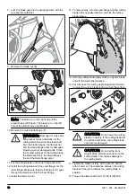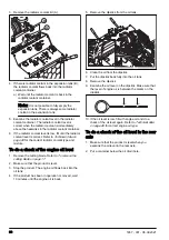
8. Lock the blade guard in the upright position with the
wire and the carabiner.
9. Remove the blade nut (E).
F
E
G
H
Note:
The blade nut on the right side of the
product has a left thread. The blade nut on the left
side of the product has a right thread.
10. Remove the outer blade flange (F).
WARNING:
Damaged or dirty parts
can prevent correct installation of the
cutting blade. Examine the blade shaft
bolt, the blade flanges, the flat washer
and the blade flange arbor for damages.
Replace worn or damaged parts. Clean
the contact surfaces of the cutting blade,
the blade shaft bolt, the blade flanges
the and the blade flange arbor.
11. Put the cutting blade on the inner flange arbor (G).
12. Install the cutting blade and the outer flange into the
inner flange. Make sure that the locking pin (H) goes
through the blade and into the inner flange.
13. Install the blade nut (E).
14. To remove play, turn the outer flange and the cutting
blade in the opposite direction of which the cutting
blade rotates.
15. Hold the cutting blade tightly while you tighten blade
nut with the blade shaft wrench.
16. Push the lever for cutting depth adjustment forward
to lower the cutting blade until it touches the surface.
CAUTION:
Do not lower the cutting
blade too quickly. If the cutting blade hits
the surface with force, the cutting blade
can become damaged.
CAUTION:
Do not let the front
weight of the product push down on the
cutting blade. This causes damage to
the cutting blade.
17. Tighten the blade nut fully. Hit the wrench handle
with a hammer. The resistance between the cutting
blade and the ground keeps the cutting blade in
position.
18. Torque the blade shaft bolt to 150 lb-ft (203 Nm).
16
1657 - 001 - 08.09.2021
Summary of Contents for FS 4600 G II
Page 165: ...1657 001 08 09 2021 165 ...
Page 166: ...166 1657 001 08 09 2021 ...
Page 167: ...1657 001 08 09 2021 167 ...


