48
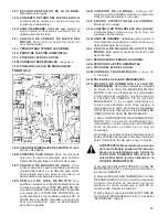
FIGURE 4
4A. BLADESHAFT BEARING SEALS
4B. FRONT WHEEL BEARINGS
4C. FRONT AXLE PIVOT BEARINGS
4D. HYDRAULIC CYLINDER PIVOT PIN
4E. REAR AXLE
4F. HYDRAULIC WHEEL MOTOR
4G. RAISE LOWER CYLINDER
4H. LINEAR ACTUATOR
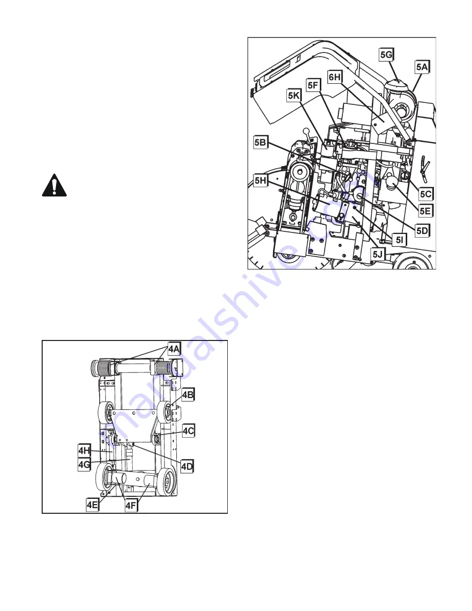
FIGURE 5
5A. AIR FILTER ASSEMBLY:
Includes
a) Housing
b) Cover
c) Primary Outer Element:
Clean or replace when
AIR RESTRICTION INDICATOR (1N) shows the
RED warning.
d) Inner Safety Element:
DO NOT CLEAN this
filter element. Replace 1 time per year or if it
becomes damaged.
5B. ENGINE OIL DIPSTICk:
Check Engine Oil Level
Here. Dipstick indicates oil level. See engine opera-
tion manual for more information.
5C. ENGINE OIL FILL:
Fill engine with recommended
oil at this location. Use SAE 15W40 API Class CF,
CF-4, CG-4, or CI-4 engine oil. See engine
operation manual for more information.
5D. ENGINE OIL FILTER:
See engine operation
manual for more information.
5E. FUEL TANk FILL:
Fill the fuel tank at this location.
5F. FUEL FILTER:
5G. AIR FILTER RAIN CAP
5H. D.C. (direct current) LIFT PUMP:
Raises and
lowers the saw.
5I. HYDRAULIC RESERVOIR FILL:
Fill and check
hydraulic system fluid here.
5J. HYDRAULIC OIL RESERVOIR:
1.5 Quart Capacity
(1.42 Liter)
5k. HYDRAULIC FILTER:
Filters hydraulic
system fluid.
5L. ----
3-2M. V-BELTS: Set of 4, 3 Groove
3-2N. GEARBOX PULLEY:
3-2O. GEARBOX SHIFT LEVER:
Use to change output
speed of the ENGINE GEARBOX (3-2A). Three-
Speeds and two Neutral positions are available.
GEARBOX SHIFT LEVER positions (1, 2, and 3)
are color coded to match, among others, Gearbox
Range / Blade RPM decal. GEARBOX SHIFT
LEVER Operation:
1) Turn ENGINE START SWITCH (1H) to OFF
(“0”) position. Always turn Engine OFF before
shifting gearbox!
2) Verify that pulley size, flange size, and
blade shaft speed are correct for the blade
size being mounted.
WARNING: Serious injury can occur to the
operator or people in the work area if the
rotational speed (n/min) of the DIAMOND
BLADE (2E) exceeds the maximum speed (n/
min) marked on the DIAMOND BLADE (2E).
3) Lift GEARBOX DETENT KNOB (3-2P) and twist
to hold in “OPEN” position.
4) Move GEARBOX SHIFT LEVER (3-2O) to
required gear. A slight “rocking motion” of the
gearbox output shaft (or BLADE SHAFT) may
improve shifting.
5) Twist and lower GEARBOX DETENT KNOB
(3-2P) back to original “LOCKED” position.
3-2P. GEARBOX DETENT kNOB:
Locks GEARBOX
SHIFT LEVER (3-2O) in position. See GEARBOX
SHIFT LEVER (3-2O) for operation.
Summary of Contents for FS 4800 D
Page 7: ... NOTES NOTAS REMARQUE ...
Page 31: ...31 NOTES NOTAS REMARQUE ...
Page 37: ...37 FS 4800 D DIESEL SPECIFICATIONS Standard CE Models ...
Page 39: ...39 ESPECIFICACIONES DE DIESEL FS 4800 D Modelos estándar y CE ...
Page 41: ...41 SPÉCIFICATIONS DU FS 4800 D DIESEL Modèles standards et CE ...
Page 112: ...542 20 10 97 2006 44 ...


