55
• Adjustments can be made while sawing or not sawing.
• Visually confirm the axle movement and direction.
Standard Model
Saw with Manual Axle Adjustment
• The axle (4E) is adjusted by turning the M12 MANUAL
AXLE ADJUSTMENT BOLT (1CC) located at the rear
lower left of saw frame.
• If the saw steers to the RIGHT while sawing, turn
the MANUAL AXLE ADJUSTMENT BOLT (1CC)
COUNTERCLOCKWISE.
• If the saw steers to the LEFT while sawing,
turn the MANUAL AXLE ADJUSTMENT BOLT
(1CC) CLOCKWISE.
Rear Pivot Model
(Saw with Differential Pivot option):
• Simply bear against the HANDLEBARS (6G) to hold the
saw on the cutting line. DO NOT shift the DIFFERENTIAL
SWITCH (1J) from the Center “Lock” position. The Left,
“Pivot”, position of the DIFFERENTIAL SWITCH (1J) is
NOT for adjusting the straight line sawing of the saw.
10
Maintenance
(See Figures 1-6)
Before performing any maintenance, ALWAYS
park the machine on a level surface with the
Engine OFF and the ENGINE START SWITCH
(1H) in the “0” (OFF) position.
After each use CLEAN the machine.
LUBRICATION:
ENGINE OIL:
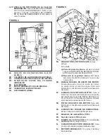
Check daily (5B). Change Engine Oil and
ENGINE OIL FILTER (5D) after every 100 HOURS of
operation. See engine manual for recommended oil. SAE
15W40 API Class CF, CF-4, CG-4, or CI-4 engine oil is
generally recommended. Capacity is 7.8 quarts (7.4 liters)
with ENGINE OIL FILTER (5D). Align oil level with upper
mark on ENGINE OIL DIPSTICK (5B). Use ENGINE OIL
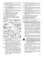
DRAIN VALVE (3-1I, 3-2I) to drain engine oil:
• Remove DIAMOND BLADE (2E), and then lower saw
to a horizontal position.
• Raise and secure ENGINE HOOD (6E).
• Put a container, large enough to contain the engine
oil capacity, near the end of the oil drain hose. Open
ENGINE OIL DRAIN VALVE (3-1I, 3-2I) and allow
contents to drain into the container. Dispose of the used
engine oil in an environmentally safe manner. Securely
close ENGINE OIL DRAIN VALVE (3-1I, 3-2I). Fill with
recommended oil until oil level aligns with the upper
mark on ENGINE OIL DIPSTICK (5B).
LUBRICATE EVERY 100 HOURS:
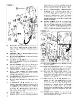
• Front Axle Pivot Bearings (4C)
LUBRICATE EVERY 250 HOURS:
• Bladeshaft Seals and Bearings (4A) 2 Pumps only
HYDRAULIC SYSTEM:
Refer to Section 12 -“Hydraulic System”
ENGINE GEARBOX (3-1A, 3-2A):
• Change oil after every 500 hours of operation. Use SAE
75W90 synthetic gear lubricant.
DO NOT OVERFILL! Fill only to “Check Port” or excess
will overflow.
Single Speed ENGINE GEARBOX (3-1A):
Oil Capacity
is 32 oz. (USA) (0.946 Liter)
Three Speed ENGINE GEARBOX (3-2A):
Oil Capacity
is 60 oz. (USA) (1.77 Liter)
• Drain cooling water from Water Drain Valve (3-1C, 3-2C)
to prevent rust and freeze damage (Every Day).
COOLING SYSTEM:
The engine cooling fluid is 50/50 anti freeze/water mixture.
See engine manual for recommendations.
• Clean the RADIATOR AIR FILTER ELEMENT (1DD)
every 50 hours or when required, replace if damaged.
Always keep RADIATOR AIR FILTER ELEMENT (1DD)
in place.
• Check hoses and hose clamps for damage and
looseness. Tighten or replace as required.
• Check Coolant Freeze Protection yearly.
• Flush and Clean radiator and cooling system every
500 hours.
• Maintain at least 1/4 full coolant level in RADIATOR
COOLANT OVERFLOW BOTTLE (1Y) when engine
is cool.
AIR FILTER:
• Clean the Air Filter Outer Element (5A) when the AIR
RESTRICTION INDICATOR (1N) Red Signal appears.
DO NOT clean the Inner Safety Element (5A)!
To change or clean the air filter element:
• Remove the Air Filter Housing (5A) by opening the
two (2) Air Filter Housing Clamps, and pulling the
housing off.
• Pull the Air Filter Outer Element out of the filter housing
and replace, or clean by using low pressure compressed
air [2.75 bars (40 psi) - MAXIMUM)] from the inside
out. DO NOT clean the filter element by tapping it
on the ground or other objects, this will damage the
filter element!
• Install the new or cleaned Air Filter Outer Element by
pushing it into the housing.
• Install the Air Filter Housing (5A) and close the two (2)
Air Filter Housing Clamps (5A).
The two (2) Air Filter Housing Clamps (5A)
can NOT be closed unless the Air Filter Outer
Element is properly installed.
Summary of Contents for FS 4800 D
Page 7: ... NOTES NOTAS REMARQUE ...
Page 31: ...31 NOTES NOTAS REMARQUE ...
Page 37: ...37 FS 4800 D DIESEL SPECIFICATIONS Standard CE Models ...
Page 39: ...39 ESPECIFICACIONES DE DIESEL FS 4800 D Modelos estándar y CE ...
Page 41: ...41 SPÉCIFICATIONS DU FS 4800 D DIESEL Modèles standards et CE ...
Page 112: ...542 20 10 97 2006 44 ...


