background image

English - 39

Piston and cylinderr

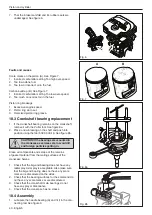
8.  Remove the circlips (A) and press out the gudgeon 

pin (B). Remove the piston. See Figure 3.

9.  Remove the piston ring (C). 


18.2 Cleaning and inspection

Clean all parts, scrape off all the remains of any gasket 
material and scrape off carbon deposits from the follo-
wing surfaces:

1.  The piston crown.
2.  Top of the cylinder bore (inside).
3.  The cylinder exhaust port.
4.  The decompression valve.
5.  Base of the cylinder and/or crankcase

Check the following:

1.  That the cylinder’s surface coating is not worn. Es-

pecially in the upper end of the cylinder.

2.  That the cylinder is free of score marks. See figure 

4.

3.  That the piston is free of score marks. Minor 

scratches can be polished off with fine emery paper.

4.  That the piston ring is not burnt into its groove. 


5.  Measure the wear on the piston ring by placing it the 

cylinder and measuring the gap. See figure 5. The 
clearance must not exceed 1 mm.

6.  That the needle bearing is undamaged. 


 Fig. 3

A

B

C

A

 Fig. 4

 Fig. 5

Summary of Contents for H130 Mark II

Page 1: ...English 1 Workshop manual H130 H135 Mark II English ...

Page 2: ...2 6 Chain catcher 15 7 Muffler 16 8 Start stop switch 17 9 Throttle trigger lockout throttle trigger and spring 19 10 Starter 21 11 Ignition system 23 12 Flywheel 24 13 Centrifugal clutch 26 14 Lubrication system 27 15 Carburettor 28 16 Tank unit 35 17 Anti vibration system 37 18 Piston and cylinder 38 19 Bar bolt 42 20 Test the ignition 43 21 Troubleshooting 44 ...

Page 3: ...chainsaw in question 1 5 Layout This Workshop Manual can be used in two different ways For the repair of a particular system on the chainsaw Dismantling and Assembly of the entire chainsaw Repair of a particular system When a particular system on the chainsaw is to be repaired proceed as follows 1 Look up the page for the system in question 2 Carry out the sections Dismantling Cleaning and inspect...

Page 4: ...After test running do not touch the muffler until it has cooled Risk of burn injuries Insufficient lubrication of the chain can result in the chain breaking which can cause serious or even life threatening injury Ensure that the spring in the starter does not fly out and cause personal injury If the spring tension is activated on the starter pulley when it is to be taken up the spring can fly out ...

Page 5: ...ainsaw casing 1 4 Symbols in this Workshop Manual This symbol indicates a risk of personal injury if instructions are not followed Choke Fuel pump Fuel filler Stop switch Saw chain oil filler Chain brake Use protective gloves Use protective goggles Introduction and safety regulations ...

Page 6: ...ain speed Chain pitch Drive link cm inch at maximum power m s mm inch mm inch 130 35 5 40 6 14 16 22 3 m s at 9000 rpm 9 5 0 375 1 3 0 05 135 35 5 40 6 14 16 22 3 m s at 9000 rpm 9 5 0 375 1 3 0 05 Spark plug gap Ignition system Air gap Carburettor type mm inch mm inch 130 0 5 0 02 Digital MBU 84 0 3 0 01 Walbro WTA 36 135 0 5 0 02 Digital MBU 84 0 3 0 01 Walbro WTA 36 2 Technical data Technical d...

Page 7: ...uel tank volume Oil pump capacity Oil tank volume Automatic oil pump Litres US pint cm3 min Litres US pint 130 0 35 0 74 9 cm3 min at 9000 rpm 0 26 0 55 YES 135 0 35 0 74 9 cm3 min at 9000 rpm 0 26 0 55 YES Weight without Weight with bar and chain bar and chain kg lbs kg lbs 130 4 7 10 3 5 3 11 6 135 4 7 10 3 5 3 11 6 rpm OIL Technical data ...

Page 8: ...8 English 11 9 3 12 13 14 10 1 2a 4 5 6 7 8 3 Service tools Service tools 2b 2c 2d 8 9 0 7 6 8 9 0 7 6 8 9 0 7 6 ...

Page 9: ...er 503 84 40 02 9 Feeler gauges ignition gap Air gap tool 502 51 34 02 10 Tachometer Checking engine rpm 502 71 14 01 11 Adjustment screwdriver Adjustment of the carburettor 501 60 02 03 12 Assembly pliers Assembly of spark plug cap 502 50 06 01 13 Hook for fuel filter Removing fuel filter 502 50 83 01 14 Assembly fixture Dismantling assembling of the chainsaw 502 51 02 01 15 T handle Torx T10 Dis...

Page 10: ...ubricate with chain oil Lubricate with grease 4 Service data Service data T30 7 0 9 0 Nm 1st torque T30 11 0 13 0 Nm 2nd torque 19 mm 12 0 14 0 Nm 12 0 14 0 Nm 2 5 3 0 Nm T25 2 2 3 4 Nm 1 0 1 5 Nm T27 2 5 3 5 Nm T27 2 5 3 5 Nm T25 5 0 6 0 Nm 4 mm 2 0 2 7 Nm 2 8 4 0 Nm 5 mm 8 mm T25 5 6 6 8 Nm 3 0 4 0 Nm 2 5 3 0 Nm 4 mm 6 0 8 0 Nm ...

Page 11: ... 6 0 8 0 Nm T27 2 2 3 4 Nm 2 8 4 0 Nm T27 2 8 4 0 Nm T25 2 5 3 5 Nm 13 mm 21 7 24 4 Nm 13 mm 11 27 Nm 2 5 3 5 Nm T20 0 9 1 4 Nm T27 2 5 3 5 Nm 1 9 3 0 Nm T20 3 4 4 5 Nm 4 mm 2 8 4 0 Nm 4 mm T27 2 2 3 4 Nm 1 9 3 0 Nm 4 mm 13 5 20 3 Nm T25 2 5 3 5 Nm ...

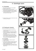
Page 12: ...e Figure 1 3 Carefully tighten the clutch housing in a vice Re lease the brake by using the kickback guard as a tool See Figure 2 4 Loosen the screws and carefully remove the cover over the brake spring Make sure the spring does not fly out See Figure 3 5 Hold one hand over the brake spring press a nar row screwdriver in between the rear section of the spring and the clutch cover Carefully pry upw...

Page 13: ...g with grease See Figure 6 Secure the circlip A See Figure 6 2 Grip the clutch cover in a vice Compress the spring with a wide screwdriver and press it down with your thumb See Figure 7 WARNING Make sure the spring does not fly out and cause injury Wear eye protection 3 Fit the cover over the chain brake spring and tighten the screws See Figure 3 4 Tension the brake spring by using the kickback gu...

Page 14: ...ows 1 Hold the chainsaw over a stable surface as shown in Figure 9 The distance between the bar and surface is given in the table below Bar length L Height H 15 28 inch 30 40 cm 2 Let go of the front handle and let the chainsaw pivot round on the rear handle 3 When the bar hits the surface the chain brake should cut in Fig 9 H L ...

Page 15: ...e clutch cover 2 Dismantle the bar and chain 6 2 Cleaning and inspection Inspect the chain catcher and replace it if it is damaged See figure 1 6 3 Assembly 1 Fit the bar and chain 2 Adjust the tension of the chain 3 Fit the clutch cover Tighten the nuts to the correct torque See Service data ...

Page 16: ...omponents and check the following 1 That the spark arrester is intact 2 That the muffler and muffler mounting are not cracked or in any way defect 3 That the gasket is undamaged CAUTION Replace the gasket if it is damaged The gasket has to be fitted correctly against the muffler 7 3 Assembly 1 Clean the contact surfaces to the gasket cooling plate and cylinder 2 If the chainsaw is fitted with a sp...

Page 17: ...n Carefully clean and check all components See Figure 3 Parts must be replaced if cracked or if they show signs of other defects Always use original spare parts 8 3 Assembly 1 If the start stop switch has been replaced fit the new start stop switch to the air filter holder See Figure 3 2 Fit the cable E See call out in Figure 2 3 Carefully attach the air filter holder B to the carburettor Make sur...

Page 18: ...ting a multimeter to the blue cable and the cylinder earth See Figure 4 NOTE The switch must be in the on position to give the correct reading The resistance must not be higher than 0 5 Ω when the switch is in the on position The stop switch is in the ON position when the button is held down and in the OFF position the button is neutral Fig 4 ...

Page 19: ... 3 Remove the antivibration element B See Figure 1 4 Remove the chain catcher C See Figure 1 5 Remove the antivibration element D See Figure 1 6 Remove the screw E holding the antivibration ele ment F See Figure 2 7 Remove the throttle wire G See Figure 3 8 Remove the fuel hose H and the suction hose I from the carburettor See Figure 3 Throttle trigger lockout throttle trigger and spring Fig 2 Fig...

Page 20: ...ts Check that the spring is intact and retains all its ten sion 9 3 Replace a defect throttle cable 1 Attach the wire to the throttle trigger Pull the wire through the handle See Figure 6 9 4 Assembly 1 Insert the throttle control O into the handle See Figure 6 2 Insert the throttle trigger into the handle Attach the throttle trigger to the handle by knocking the pin L into the handle 3 Put togeth...

Page 21: ...rter cord The dogs on the starter pulley That the pawls on the flywheel are intact and that the spring is back towards the centre and moves freely The easy starter spring only 135 3 Grease the spring in the starter pulley 10 3 Assembly WARNING If the spring is tensioned on the starter pulley it can fly up and cause personal injury 1 If a new spring is to fitted make sure that the spring is placed ...

Page 22: ...rrectly tensioned See Figure 5 2 Pull out the cord completely 3 In this position it should be possible to turn the pul ley by hand an additional 1 2 3 4 turn 4 Fit the starter on the crankcase Check that the starter pulley is fitted correctly against the crank case by lightly pull the starter cord Tighten the screws See Figure 1 Fig 5 ...

Page 23: ...ace the damaged parts with new ones Always use original parts 11 4 Assembly 1 Attach the ignition module to the cylinder without tightening the screws See Figure 1 2 Turn the flywheel so that the magnets are in line with the ignition module Fit the the plastic feeler gauge 502 51 34 02 Set a distance of 0 3 0 1 mm between the ignition module and magnet The measurement applies to the two lowest lug...

Page 24: ... piston stop 575 29 36 01 in spark plug hole See figure 1 4 Loosen the screws holding the ignition module but do not remove them 5 Remove the flywheel nut 6 Remove the screws A pawls B springs C and washers D See Figure 2 7 A special tool 502 51 49 02 from Husqvarna is required to dismantle and assemble the flywheel Center the tool on the crankshaft Select the appropriate screw supplied with the t...

Page 25: ...f damage 12 3 Assembly 1 Fit the washers D springs C pawls B and screws A See Figure 5 2 Clean crankshaft to remove grease or oil 3 Fit the flywheel onto the crankshaft pin Turn the flywheel until the key fits into the key slot on the shaft See figure 6 4 Tighten the nut for the flywheel 5 Remove the piston stop See figure 1 6 Turn the flywheel so that the magnets are in line with the ignition mod...

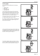
Page 26: ...o wear on the chain drive sprocket That the needle bearing is in good condition and that there is no damage on the journal surface on the crankshaft That the friction surface on the clutch drum is intact and that the bearing surface is undamaged That the thickness on the clutch shoes is no less than 1 mm at the most worn point See Figure 3 If the thickness is less change the entire clutch 13 3 Ass...

Page 27: ...embly 1 Thread new worm spring into tool Make sure that it is fully seated in tool thread See Figure 3 2 Place the tool with the spring assembly onto crank shaft 3 Lightly tap end of tool until spring is aligned into the retention groove on crankshaft The tool makes sure the spring is installed at the correct depth 4 Unthread tool off of installed spring Use a scrench hex driver if required to rem...

Page 28: ...ed and power output See Figure 1 The mixing venturi B houses the choke throttle valve and diffuser jets Here air is mixed with the fuel to give a fuel air mixture that can be ignited by the ignition spark See Figure 2 In the pump unit C fuel is pumped from the fuel tank to the metering unit One side of the pump diaphragm is connected to the crankcase and pulses in time with the pressure changes in...

Page 29: ...gure 5 the throttle valve I and J is closed and the choke valve H is open Air is sucked in through an aperture in the throttle valve and a small amount of fuel is supplied through the dif fuser jet D see Figure 5 In the part throttle mode see Figure 6 the throttle valve I is partially open and the choke valve H is open Fuel is supplied through the diffuser jets D and E The throt tle valve J starts...

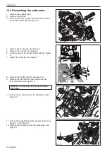
Page 30: ... filter holder B See Figure 9 7 Detach the cable E See Figure 9 8 Remove the throttle wire F See Figure 10 9 Remove the fuel hose G and suction hose H from carburettor See Figure 10 NOTE Do not use any sharp tools to loosen the hoses 10 Pull out the air valve I from the inlet pipe J See Figure 10 11 Pull out the carburettor and the air valve I from the flange L See Figure 11 12 Remove the air valv...

Page 31: ...ody Air can penetrate into the blood circulation which means mortal danger Use compressed air to dry the petrol on the components Direct the air through all channels in the carburettor housing and ensure that they are not blocked Check the following That the gasket pump and control diaphragms are undamaged as well as the gasket between the carburettor body and the autotuner That there is no play o...

Page 32: ...ing the carburettor Pressure testing should be carried out with the carbu rettor fully assembled The test must always be done after the carburettor has been repaired but can also be carried out when troubleshooting before the carburettor is taken apart Test 1 See Figure 14 and carry out the following check 1 Connect pressure tester to the carburettor fuel inlet 2 Lower the carburettor into a beake...

Page 33: ...ch the air valve I to the inlet pipe J See Figure 11 4 Fit the carburettor on the flange L Figure 11 5 Attach the throttle wire F to the carburettor as outlined in Figure 10 6 Attach the fuel hose G to the carburettor as out lined in Figure 10 7 Attach the suction hose H to the carburettor as outlined in Figure 10 8 Attach the ignition cable E to the start stop switch and fit the air filter holder...

Page 34: ...cal conditions e g climate altitude fuel and type of 2 stroke oil The carburettor is equipped with three adjustment op tions L Low speed jet H High speed jet T Idling adjustment The L and H jets adjust the fuel flow to match the air flow that the throttle valve opening allows Turning them clockwise makes the fuel air mixture weaker less fuel and turning them counter clockwise makes the fuel air mi...

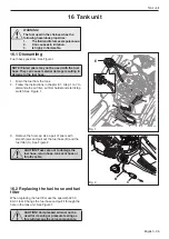
Page 35: ...r 8 1 Step 1 to 7 to dismantle the air filter air filter holder and start stop switch See Figure 1 3 Remove the fuel cap Use a pair of pliers with smooth jaws and pull out the fuel hose B and the fuel filter C See Figure 2 CAUTION Take care not to damage the fuel hose return hose tank vent hose or throttle cable 16 2 Replacing the fuel hose and fuel filter When replacing the fuel filter use the sp...

Page 36: ...nd return hose A from the primer bulb E See Figure 1 16 4 Cleaning and inspection Clean all parts and check that the fuel hose is intact 16 5 Assembly 1 Make sure the fuel filter is attached to the fuel hose 2 Follow the instructions in chapter 8 1 Step 1 to 9 in the reverse order ...

Page 37: ...emove the screw A holding the antivibration ele ment B See Figure 1 3 Remove the antivibration element B See Figure 1 4 Remove the chain catcher C See Figure 1 5 Remove the antivibration element D See Figure 1 6 Remove the screw E holding the antivibration ele ment F and See Figure 2 7 Remove the anti vibration element See Figure 2 17 2 Cleaning and inspection Clean and inspect all parts 17 3 Asse...

Page 38: ...vibration element Oil system 2 Detach the fuel hose and return hose 3 Detach the throttle wire 4 Remove the tank unit and front handle 5 Remove the carburettor and the manifold 6 Remove the five screws holding the crankcase to the cylinder See Figure 1 7 Remove the cylinder See Figure 2 CAUTION Exercise care so that dirt and foreign particles do not get into the crankcase 18 Piston and cylinder Fi...

Page 39: ...The decompression valve 5 Base of the cylinder and or crankcase Check the following 1 That the cylinder s surface coating is not worn Es pecially in the upper end of the cylinder 2 That the cylinder is free of score marks See figure 4 3 That the piston is free of score marks Minor scratches can be polished off with fine emery paper 4 That the piston ring is not burnt into its groove 5 Measure the ...

Page 40: ...ew brearing on the shaft and push into position using the tool 502 50 30 18 See figure 8b CAUTION If the bearings are mounted in the crankcase exercise care to avoid dirt and foreign particles getting in Clean all components and scrape of the remains of gasket material from the mating surfaces of the crankcase halves 1 Check that the big end bearing does not have any radial play Axial play is acce...

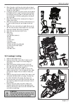
Page 41: ...r filter and air filter holder Spark plug Cylinder cover 18 5 Leakage testing 1 Remove the cylinder cover 2 Remove the air filter the air filter holder and the carburettor See chapter 15 4 Dismantling the carburettor 3 Attach the pressure testing covers A B and spacing sleeves D Tighten the pressure testing cover B with the nuts See Figure 10 4 Loosen the screws on the muffler and press the rubber...

Page 42: ...Secure steel wire to the outer part of the new bar bolt thread the steel wire through the oil tank and out through the bolt hole See Figure 3 2 Pull the steel wire so the bolt comes out of its hole See Figure 3 3 Check that the bolt s square head fits in the washer which is positioned inside the oil tank 4 Pull out the bar bolt using its nut Place two spacer between the nut and chain guard plate S...

Page 43: ...st the knob to 6 mm gap between the two electrodes read 6 marks on the corresponding scale 4 Pull firmly in the starter handle 5 A clear blue spark will be visible between the elec trodes if the ignition works properly The ignition system must be capable of producing a strong spark or the engine will have performance prob lems particularly under load 20 Test the ignition Fig 1 ...

Page 44: ...tle return spring Bent valve axle stop Faulty diffuser jet Too rich idling Worn needle needle tip Worn lever arm in the control system Leaking diaphragm cover plate Worn needle needle tip Leaking diaphragm cover plate Worn lever arm in the control system Faulty diffuser jet Uneven idling Blocked fuel filter Blocked fuel line Leaking inlet hose rubber Loose carburettor mounting Worn throttle valve ...

Page 45: ...ubber Loose carburettor mounting Control system set too low Leaking control system air or fuel Control system incorrectly as sembled Loose diaphragm Hole in diaphragm Leaking diaphragm cover plate Acceleration and retardation Does not accelerate Blocked air filter Tank venting clogged Blocked fuel filter Blocked fuel line Loose or faulty fuel hose Blocked impulse channel The cover on the carburett...

Page 46: ...46 English 2019 02 27 115 98 13 26 ...

Reviews: