BODY AND TRIM
Front Body Components
Page 4-4
2005 HUV4420 Gasoline and HUV4420-D Diesel Vehicle Maintenance and Service Manual
4
INSTRUMENT PANEL INSTALLATION
1. Connect the wiring to the electrical components mounted on the instrument panel.
See Wiring Diagram
on page 11a-6 (gasoline vehicles) or Wiring Diagram on page 11b-6 (diesel vehicles).
2.
Gasoline vehicles:
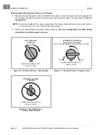
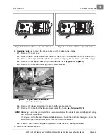
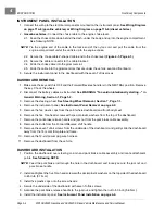
Connect the choke cable to the engine choke lever.
2.1. Feed the choke cable down behind the dash, under the body, and up into the engine compartment.
See following NOTE.
NOTE:
Tie the engine end of the cable to the loose end of the nylon cord, and pull the cable from the
engine compartment under the vehicle up to the engine choke.
2.2. Secure the choke cable Z-shaped cable end to the choke lever
(Figure 4-3, Page 4-3)
.
2.3. Secure the cable connector to the cable bracket.
2.4. Slide the choke cable into the grommet slot.
2.5. Slide the cable into the grommet slots that are under the vehicle seat and floorboard.
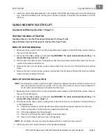
3. Secure the instrument panel to the dashboard with the seven Tuflok screws.
DASHBOARD REMOVAL
1. Make sure the key switch is OFF and the Forward/Reverse handle is in the NEUTRAL position. Remove
the key. Chock the wheels.
2. Disconnect the battery cables as instructed.
See WARNING “To avoid unintentionally starting...” in
General Warning, Section 1, Page 1-2.
3. Remove the steering wheel.
See Steering Wheel Removal, Section 7, Page 7-1.
4. Remove the instrument panel.
See Instrument Panel Removal on page 4-2.
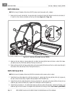
5. Remove the five plastic caps from the point where dashboard and front body meet.
6. Remove the five Torx-head screws with special plastic washers from the top of the dashboard.
7. Remove the park brake release handle and jam nut from the park brake cable assembly.
8. Remove the knob from the Forward/Reverse shift handle.
9. Remove the seven Tuflok screws from the underside of the dashboard, and gently slide the dashboard
away from the floor mat trim plate and frame.
10. Remove the 12-volt power plug wire harness.
11. Remove the dashboard from the vehicle.
DASHBOARD INSTALLATION
1. Position the dashboard over steering column and park brake cable assembly and locate attachment
points.
See following NOTE.
NOTE:
Feed the park brake rod through the hole in the dashboard, and loosely secure the jam nut and
park brake handle.
2. Install and tighten the five Torx-head screws with special plastic washers on the top side of the dashboard
to 45 in-lb (5.1 N·m).
3. Install five plastic caps onto the screw heads.
4. Secure the underside of the dashboard with seven Tuflok screws.
5. Advance the park brake release handle to the jam nut, and tighten the nut to 50 in-lb (5.6 N·m).
6. Install the instrument panel.
See Instrument Panel Installation on page 4-4.
Summary of Contents for HUV4420
Page 1: ... 5 5 2 4 56 56 3 3 6 3 4 3 26 5 ...
Page 2: ......
Page 16: ...Page xiv 2005 HUV4420 Gasoline and HUV4420 D Diesel Vehicle Maintenance and Service Manual ...
Page 20: ...1 ...
Page 38: ...4 ...
Page 68: ...5 ...
Page 74: ...6 ...


