HYDRAULIC AND PARK BRAKE SYSTEMS
Park Brake System
Page 5-28
2005 HUV4420 Gasoline and HUV4420-D Diesel Vehicle Maintenance and Service Manual
5
PARK BRAKE PEDAL
Park Brake Pedal Removal
1. Chock the wheels and release the park brake.
2. Remove the dashboard.
See Dashboard Removal, Section 4, Page 4-4.
3. Remove the front body.
See Front Body Removal, Section 4, Page 4-5.
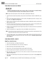
4. Remove the front park brake cable end from the park brake pedal.
5. Remove the three bolts and locknuts that secure both the park brake pedal and the pulley mounting plate
to the front part of the vehicle frame.
6. Remove the park brake pedal.
Park Brake Pedal Installation
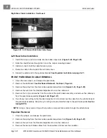
1. Secure the pulley mounting plate and park brake assembly with three bolts and locknuts. Tighten the
hardware to 15 ft-lb (20 N·m).
2. Install the park brake cable.
See Front Park Brake Cable Installation on page 5-27.
3. Install the dashboard.
See Dashboard Installation, Section 4, Page 4-4.
4. Install the front body.
See Front Body Installation, Section 4, Page 4-5.
5. Adjust the brake cable equalizer.
See Park Brake Cable Adjustment on page 5-24.
PARK BRAKE PULLEYS
Park Brake Pulley Removal
1. Chock the wheels and release the park brake.
2. Remove the dashboard.
See Dashboard Removal, Section 4, Page 4-4.
3. Remove the front body.
See Front Body Removal, Section 4, Page 4-5.
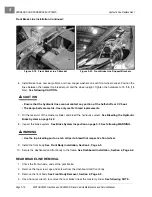
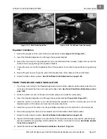
4. Remove the spring from the driver side equalizer adjustment rod
(Figure 5-25, Page 5-27)
.
5. Remove the nuts from the threaded adjustment rod on the cable end.
6. Remove the cable end from the equalizer bracket.
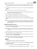
7. Remove the C-clip and the cable eye from the park brake pedal
(Figure 5-26, Page 5-27)
.
8. Tie a heavy nylon string to the threaded adjustment rod, and remove the cable from the vehicle body at
the park brake pedal. Allow the nylon string to travel under the body to the park brake pedal.
9. Remove the three bolts and locknuts that secure both the park brake assembly and the pulley mounting
plate assembly to the front part of the vehicle frame.
10. Remove the four bolts, washers, and locknuts from each pulley assembly.
11. Remove the two pulleys.
Lower Frame Pulley Removal
NOTE:
It is not necessary to remove the floorboard for installation and removal of the lower pulley assem-
bly. All fasteners are accessible from the rear side of the pulley bracket.
1. Remove the four bolts, washers, and locknuts that secure the lower pulley assembly to the bottom of the
frame under the floorboard.
2. Remove the pulley.
Summary of Contents for HUV4420
Page 1: ... 5 5 2 4 56 56 3 3 6 3 4 3 26 5 ...
Page 2: ......
Page 16: ...Page xiv 2005 HUV4420 Gasoline and HUV4420 D Diesel Vehicle Maintenance and Service Manual ...
Page 20: ...1 ...
Page 38: ...4 ...
Page 68: ...5 ...
Page 74: ...6 ...

