English-
102
REPAIR INSTRUCTIONS
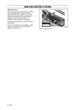
Replacing the switch for driver’s seat
1.
Pull apart the connector under the
driver's seat and release the shock
absorber from the chassis.
2.
Remove the driver’s seat.
3.
Remove the seat cushion from the
underframe.
4.
Remove the switch from the seat
cushion.
5.
Remove the switch from the cable. The
connector is locked by a plastic catch.
6.
Assemble in reverse order.
Sensors
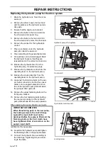
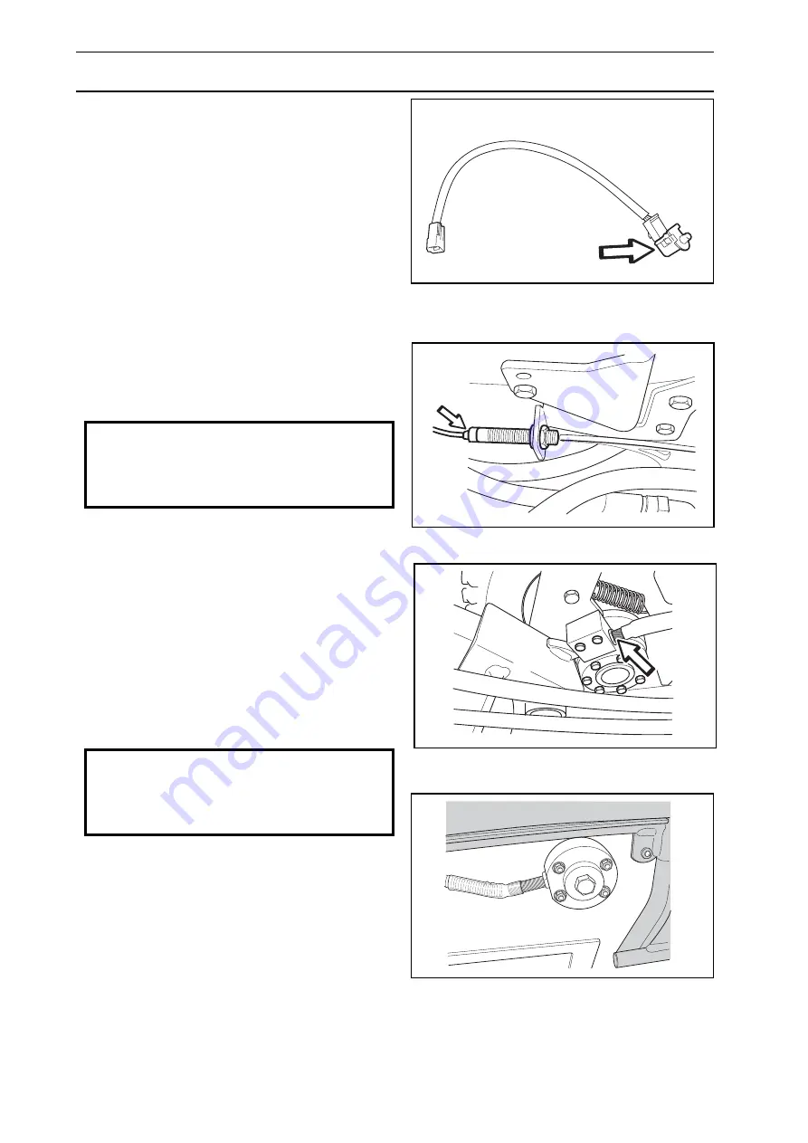
The function of the sensor can be tested with
the LED, which is integrated in the sensor.
•
Hydrostatic control (drive pedals)
•
Parking brake, see page 101
•
Lifting arm
•
Differential lock pedal
Sensors are not sold separately. Replace the
cable harness with the four sensors when a
fault has been established.
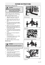
Set the distance 2-3 mm between the sensor
and its target surface. Tightening torque
30 Nm.
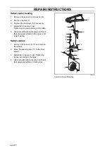
8043-111
Driver’s seat switch
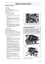
8043-171
LED in sensor drive pedals
IMPORTANT INFORMATION
The sensors only permit a 200 mA load.
Do not use a test lamp for testing.
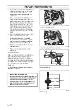
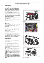
8043-137
Sensor lifting arm
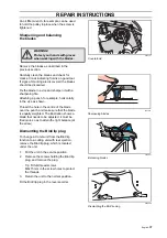
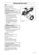
8043-175
Sensor diff lock pedal
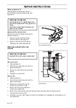
IMPORTANT INFORMATION
The sensor has a thin wall with a fine thread
and the thread strip if tightened too tight.
Summary of Contents for PT 26D
Page 1: ...Workshop manual PT26D English ...
Page 13: ...English 12 SPECIAL TOOLS ...
Page 94: ...English 93 REPAIR INSTRUCTIONS 8043 197 Cutting unit Combi 155 ...
Page 107: ...English 106 REPAIR INSTRUCTIONS ...
Page 123: ...English 122 REPAIR INSTRUCTIONS ...
Page 145: ......
Page 146: ...English 145 APPENDIXES Circuit diagram Circuit diagram 1 ...
Page 147: ...English 146 APPENDIXES Circuit diagram 2 ...
Page 148: ...English 147 APPENDIXES Circuit diagram 3 ...
Page 149: ...English 148 APPENDIXES Circuit diagram 4 ...
Page 150: ...English 149 APPENDIXES Circuit diagram 5 ...
Page 151: ...English 150 APPENDIXES Circuit diagram 6 ...
Page 152: ...English 151 APPENDIXES Circuit diagram 7 ...
Page 153: ...English 152 APPENDIXES Circuit diagram 8 ...
Page 154: ...English 153 APPENDIXES Circuit diagram 9 ...
Page 155: ...English 154 APPENDIXES Circuit diagram 10 ...
Page 156: ...English 155 APPENDIXES Circuit diagram 11 ...
Page 157: ...English 156 APPENDIXES ...
Page 161: ...English 160 APPENDIXES 8043 160 Circuit board placement ...
Page 162: ...English 161 APPENDIXES Hydraulic diagram 8043 247 Hydraulic diagram ...
Page 163: ...English 162 APPENDIXES ...
Page 167: ...2009W18 115 08 30 26 ...


