English-
114
REPAIR INSTRUCTIONS
Replacing the hydraulic pump for the drive system
1.
Drain the hydraulic tank. Treat the oil as
waste oil.
2.
Remove the driver’s seat, the fuel tank
and the plate over the hydraulic pump's
drive axle.
3.
Ensure that the engine cannot start.
4.
Remove the bolts to the front clutch for
the drive axle and spacer ring.
5.
Remove the bolts to the rear clutch for
the drive axle and remove the drive axle.
6.
Remove the sensor for the hydrostatic
control.
7.
Place a container under the hydraulic
pump to collect the waste oil.
8.
Clean according to the general instructions.
9.
Connections can be interchanged. Mark
the hydraulic hoses so that they are
reassembled on the correct connections.
10. Release the hydraulic lines from the
hydraulic pump. Fit protective plugs.
11. Release the hydrostatic control from the
operating lever on the hydraulic pump.
12. Release the shock absorber from the
operating lever on the hydraulic pump.
13. Loosened the fastening bolts on the sen-
sor holder a few turns so that the sensor
holder can be angled outwards and run
free of the hydraulic pump bracket when
the pump is lifted upwards.
14. Remove the upper fastening bolts on the
front pump bracket.
15. Remove the four fastening bolts holding
the rear pump bracket on the hydraulic
pump bracket and lift the pump upwards.
When replacing the pump, transfer over parts
not fitted on the new pump.
16. Assemble the hydraulic pump and tighten
the fastening bolts on the pump brackets.
17. Connect the hydraulic lines according to
the markings. Tightening torque accord-
ing to the table.
S
Model-No./Ident-No
.
Model Code
MPVO25CB
AYRA
CNNAAB
DDDRAFFANNN
***
DA
M25-2136
K-06-10-06573
Made in USA
Serial-N0.
NFO
SS
A UE
R
8043-168
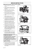
Hydraulic pump drive system
8043-113
Front clutch
8043-109
Hydrostatic control sensor
IMPORTANT INFORMATION
When transferring parts to the new pump,
the locking screws to the clutch flange
against the input shaft must not be
tightened before the pump is fitted and the
fastening bolts on the front clutch have
been tightened. Risk of axial strain on the
pump's input shaft.
8043-119
Locking screw
Summary of Contents for PT 26D
Page 1: ...Workshop manual PT26D English ...
Page 13: ...English 12 SPECIAL TOOLS ...
Page 94: ...English 93 REPAIR INSTRUCTIONS 8043 197 Cutting unit Combi 155 ...
Page 107: ...English 106 REPAIR INSTRUCTIONS ...
Page 123: ...English 122 REPAIR INSTRUCTIONS ...
Page 145: ......
Page 146: ...English 145 APPENDIXES Circuit diagram Circuit diagram 1 ...
Page 147: ...English 146 APPENDIXES Circuit diagram 2 ...
Page 148: ...English 147 APPENDIXES Circuit diagram 3 ...
Page 149: ...English 148 APPENDIXES Circuit diagram 4 ...
Page 150: ...English 149 APPENDIXES Circuit diagram 5 ...
Page 151: ...English 150 APPENDIXES Circuit diagram 6 ...
Page 152: ...English 151 APPENDIXES Circuit diagram 7 ...
Page 153: ...English 152 APPENDIXES Circuit diagram 8 ...
Page 154: ...English 153 APPENDIXES Circuit diagram 9 ...
Page 155: ...English 154 APPENDIXES Circuit diagram 10 ...
Page 156: ...English 155 APPENDIXES Circuit diagram 11 ...
Page 157: ...English 156 APPENDIXES ...
Page 161: ...English 160 APPENDIXES 8043 160 Circuit board placement ...
Page 162: ...English 161 APPENDIXES Hydraulic diagram 8043 247 Hydraulic diagram ...
Page 163: ...English 162 APPENDIXES ...
Page 167: ...2009W18 115 08 30 26 ...


