English-
116
REPAIR INSTRUCTIONS
5.
Connections can be interchanged. Mark
the hydraulic hoses so that they are
reassembled on the correct connections.
6.
Release the hydraulic lines from the valve block.
Fit protective plugs.
7.
Remove the valve block’s mounting bolts.
8.
Assemble in reverse order. Tightening Torques
for hydraulic lines as set out in the table.
Dismantling and reassembly
The flushing valve must only be dismantled if
cleaning is necessary or there is external
leakage. In other cases, replace the entire
valve.
1.
Remove the plugs with a groove marked
key handle. Keep track of springs and
spring guides.
2.
Pull out the valve slider with a pair of
needle-nosed pliers.
3.
Loosen (do not remove) the locking nut
for the pressure limiting valve, key
handle 27 mm. Count the turns and
unthread the pressure limiting valve, key
handle 13 mm. Keep track of spring and
valve cone. When the valve has been
removed, the opening pressure must be
set again after assembly.
4.
Remove all other plugs and connections.
5.
Clean the block and removed parts
carefully. Blow all channels with dry
pressurised air.
6.
Dip the slider into clean hydraulic oil.
Insert it into place and check that it
moves easily.
7.
Fit springs with spring guides and plugs.
8.
Refit the pressure limiting switch valve’s
cone, spring and valve body with default
setting according to turns counted during
dismantling. Fit the lock nut without turn-
ing the valve body
9.
Fit remaining plugs and connections.
10. Adjust the pressure limiting valve’s
opening pressure.
Replacing valve block transmission
1.
Drain the hydraulic tank.
2.
Jack up and block the machine
3.
Place a container under the valve block
to collect the waste oil.
4.
Clean according to the general
instructions.
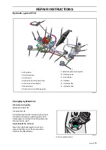
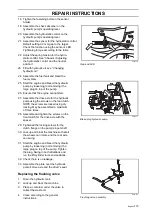
8043-188
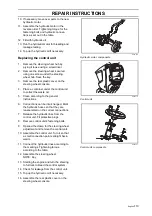
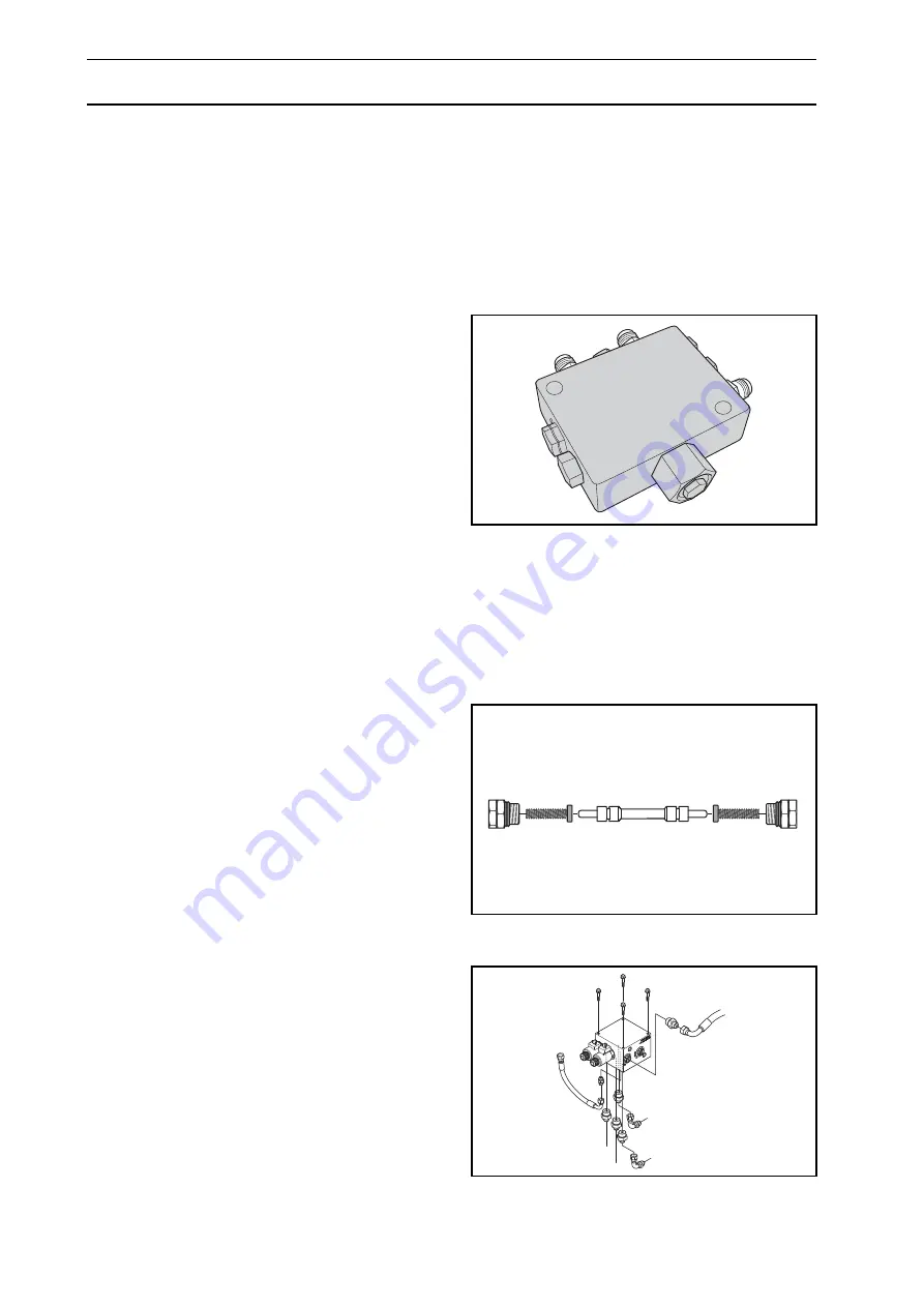
Flushing valve
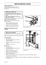
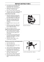
8043-189
Valve slider
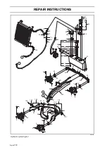
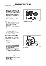
8043-125
Valve block transmission, assembly
Summary of Contents for PT 26D
Page 1: ...Workshop manual PT26D English ...
Page 13: ...English 12 SPECIAL TOOLS ...
Page 94: ...English 93 REPAIR INSTRUCTIONS 8043 197 Cutting unit Combi 155 ...
Page 107: ...English 106 REPAIR INSTRUCTIONS ...
Page 123: ...English 122 REPAIR INSTRUCTIONS ...
Page 145: ......
Page 146: ...English 145 APPENDIXES Circuit diagram Circuit diagram 1 ...
Page 147: ...English 146 APPENDIXES Circuit diagram 2 ...
Page 148: ...English 147 APPENDIXES Circuit diagram 3 ...
Page 149: ...English 148 APPENDIXES Circuit diagram 4 ...
Page 150: ...English 149 APPENDIXES Circuit diagram 5 ...
Page 151: ...English 150 APPENDIXES Circuit diagram 6 ...
Page 152: ...English 151 APPENDIXES Circuit diagram 7 ...
Page 153: ...English 152 APPENDIXES Circuit diagram 8 ...
Page 154: ...English 153 APPENDIXES Circuit diagram 9 ...
Page 155: ...English 154 APPENDIXES Circuit diagram 10 ...
Page 156: ...English 155 APPENDIXES Circuit diagram 11 ...
Page 157: ...English 156 APPENDIXES ...
Page 161: ...English 160 APPENDIXES 8043 160 Circuit board placement ...
Page 162: ...English 161 APPENDIXES Hydraulic diagram 8043 247 Hydraulic diagram ...
Page 163: ...English 162 APPENDIXES ...
Page 167: ...2009W18 115 08 30 26 ...


