English-
118
REPAIR INSTRUCTIONS
Dismantling and reassembly
1.
Remove the double solenoid valve if it is
fitted. If not, remove its cover plate. Four
O-rings are released.
2.
Remove the electric part from the sole-
noid valves by removing the plastic nut,
after which the electric part can be lifted
off from the cartridge valve.
3.
Remove the cartridge valves from the
valve block. Do not take apart the car-
tridge valves, faulty valve is replaced
completely.
4.
Remove the restrictor from port C.
5.
Remove the plugs from ports A and B.
Plugged drill conduits must not be opened
6.
Clean the block and blow all channels
with clean pressurised air. In particular,
blow clean the restrictor under
connection B.
7.
Blow clean the restrictor, to be fitted in
port C.
8.
Assemble in reverse order. The cartridge
valves are fitted in order.
long – medium – short, when the block is
turned with the restrictor facing you.
Secure the four O-rings with grease so
that they are nor squeezed.
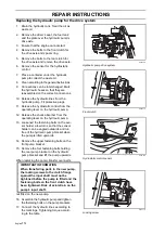
Replacing the hydraulic motor
Remark: The motors differ see the rating
plate; the right motor is marked CV and left
CCV.
1.
Remove the wheel.
2.
Clean according to the general
instructions.
3.
Drain the hydraulic tank if sealing plugs
for the hydraulic lines are not available.
4.
Release the parking brake cable from
the front hydraulic motor.
5.
Connections can be interchanged. Mark
the hydraulic hoses so that they are
reassembled on the correct connections.
6.
Place a container under the hydraulic
motor.
7.
Release the hydraulic lines from the
motor. Fit the sealing plug to prevent
leakage.
8.
Remove the fastening bolts. 10 mm allen
key on the inside.
9.
Remove the hydraulic motor.
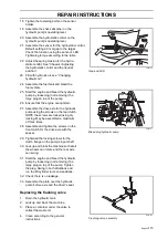
8043-191
Valve block working hydraulics
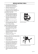
8043-115
Hydraulic motor
Summary of Contents for PT 26D
Page 1: ...Workshop manual PT26D English ...
Page 13: ...English 12 SPECIAL TOOLS ...
Page 94: ...English 93 REPAIR INSTRUCTIONS 8043 197 Cutting unit Combi 155 ...
Page 107: ...English 106 REPAIR INSTRUCTIONS ...
Page 123: ...English 122 REPAIR INSTRUCTIONS ...
Page 145: ......
Page 146: ...English 145 APPENDIXES Circuit diagram Circuit diagram 1 ...
Page 147: ...English 146 APPENDIXES Circuit diagram 2 ...
Page 148: ...English 147 APPENDIXES Circuit diagram 3 ...
Page 149: ...English 148 APPENDIXES Circuit diagram 4 ...
Page 150: ...English 149 APPENDIXES Circuit diagram 5 ...
Page 151: ...English 150 APPENDIXES Circuit diagram 6 ...
Page 152: ...English 151 APPENDIXES Circuit diagram 7 ...
Page 153: ...English 152 APPENDIXES Circuit diagram 8 ...
Page 154: ...English 153 APPENDIXES Circuit diagram 9 ...
Page 155: ...English 154 APPENDIXES Circuit diagram 10 ...
Page 156: ...English 155 APPENDIXES Circuit diagram 11 ...
Page 157: ...English 156 APPENDIXES ...
Page 161: ...English 160 APPENDIXES 8043 160 Circuit board placement ...
Page 162: ...English 161 APPENDIXES Hydraulic diagram 8043 247 Hydraulic diagram ...
Page 163: ...English 162 APPENDIXES ...
Page 167: ...2009W18 115 08 30 26 ...


