English-
133
TROUBLE SHOOTING
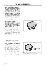
Excess flow valve in steering unit
Connect manometer 0-15 MPa (0-150 bar) to
test socket P2 on the conductor at the outlet
of the bearing pump.
Disconnect the hose (T) from the T-coupling
nearest to the vehicle centre behind the park-
ing brake lock. Plug the cable to the pump
and the drive system's valve block with a
steel plug. Lead the disconnected cable Q1
to a vessel to check for any flow.
To reach 12 MPa (120 bar) the cutting unit
must be run at top speed or the steering
turned to its end position.
If there is flow in the hose when the engine is
running and pressure is below 12 MPa
(120 bar), the excess flow valve in the
steering unit is leaky.
Gear pumpsuction filter
Same prerequisite as above.
If the pressure does not reach 12 MPa (120 bar)
and there is no flow in the hose, the gear pump
is defective or the suction filter clogged.
Axial piston pump A and B side
Normally, only one side (P3) needs to be
checked. Connect manometer 0-15 MPa
(0-150 bar) to test socket P3 on the frontside
or P4 for the backside.
Driving with all wheels jacked up:
Full speed without load P3 guideline value
1.65 MPa (16.5 bar).
Full speed ahead 2WD guideline value
4.5 MPa (45 bar).
Full speed
ahead 4WD guideline value
3.1 MPa (31 bar).
Full speed
ahead 4WD+diff lock
guideline
value
5
MPa
(50
bar).
Connect manometer 0-15 MPa (0-150 bar) to test socket P3 for the frontside.
Drive on even ground two-wheel drive with the forward pedal fully pressed The manometer should read
approx. 7-8 MPa (70-80 bar).
Drive on even ground four-wheel drive without diff lock with the forward pedal fully pressed. The mano-
meter should read approx. 3-4 MPa (30-40 bar).
Diff lock
Same prerequisite as above.
Drive forwards on four-wheel drive. Operation of diff lock should result in change of pressure to the guide-
line value on the manometer 6-7 MPa (60-70 bar).
When driving in high gear, the diff lock does not work.
8043-246
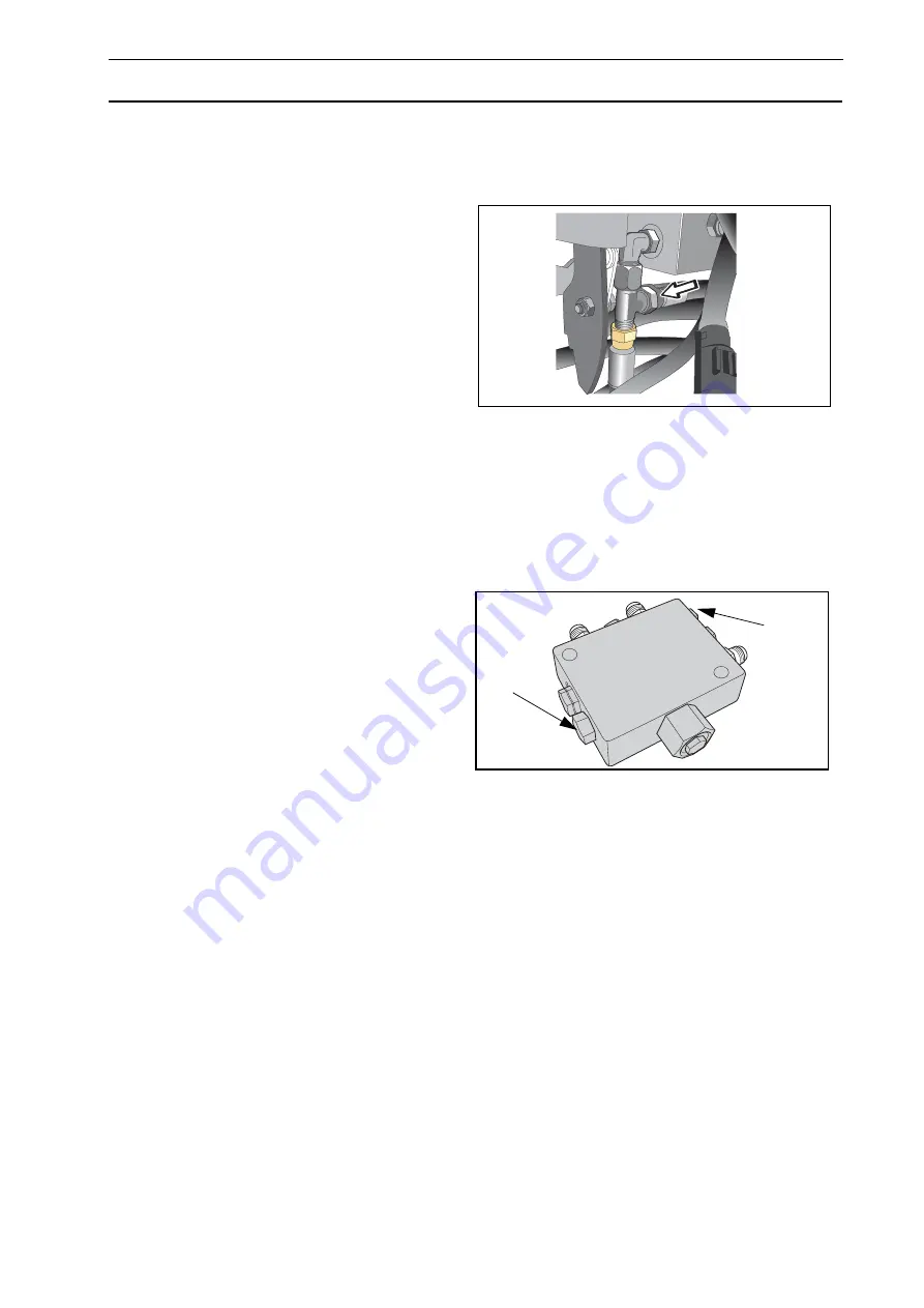
T-coupling for Q1 behind parking brake lock
8043-188
Test socket P3 forward drive and PV reversing. The
flushing valve is located on the base of the axial piston
pump.
P4
P3
Summary of Contents for PT 26D
Page 1: ...Workshop manual PT26D English ...
Page 13: ...English 12 SPECIAL TOOLS ...
Page 94: ...English 93 REPAIR INSTRUCTIONS 8043 197 Cutting unit Combi 155 ...
Page 107: ...English 106 REPAIR INSTRUCTIONS ...
Page 123: ...English 122 REPAIR INSTRUCTIONS ...
Page 145: ......
Page 146: ...English 145 APPENDIXES Circuit diagram Circuit diagram 1 ...
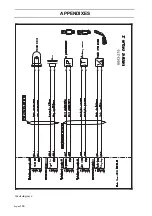
Page 147: ...English 146 APPENDIXES Circuit diagram 2 ...
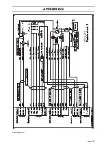
Page 148: ...English 147 APPENDIXES Circuit diagram 3 ...
Page 149: ...English 148 APPENDIXES Circuit diagram 4 ...
Page 150: ...English 149 APPENDIXES Circuit diagram 5 ...
Page 151: ...English 150 APPENDIXES Circuit diagram 6 ...
Page 152: ...English 151 APPENDIXES Circuit diagram 7 ...
Page 153: ...English 152 APPENDIXES Circuit diagram 8 ...
Page 154: ...English 153 APPENDIXES Circuit diagram 9 ...
Page 155: ...English 154 APPENDIXES Circuit diagram 10 ...
Page 156: ...English 155 APPENDIXES Circuit diagram 11 ...
Page 157: ...English 156 APPENDIXES ...
Page 161: ...English 160 APPENDIXES 8043 160 Circuit board placement ...
Page 162: ...English 161 APPENDIXES Hydraulic diagram 8043 247 Hydraulic diagram ...
Page 163: ...English 162 APPENDIXES ...
Page 167: ...2009W18 115 08 30 26 ...

