English-
77
REPAIR INSTRUCTIONS
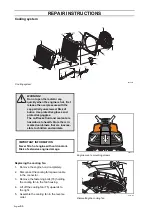
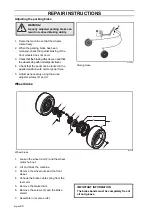
Assembling the rear axle
1.
Guide the hydraulic hoses into position
and lift the rear axle (22) onto the rear
frame (12).
2.
Lubricate the pendulum shaft (19)with
molybdenum disulphide grease and
assemble it. Tightening torque according
to the table.
3.
Connect the hydraulic hoses according
to the markings. Tightening torque
according to the table.
4.
Fit the clamp for the hydraulic hoses.
Check that the hoses do not rub against
any material, even when fully extended
in both directions and rear axle pendling.
5.
Fill with hydraulic oil.
6.
Run the hydraulic motors for bleeding
and leakage testing.
7.
Top up the hydraulic oil if necessary.
8.
Refit the rear wheels.
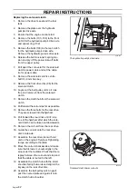
Replacing bushings for pendulum
shaft
1.
Remove the rear axle.
2.
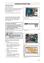
Carefully cut the old bushings (23) using
a hacksaw blade and remove them.
3.
Assemble the new bushings so that they
sit level with the hole in the rear axle.
4.
Check that there are no burrs on the
pendulum shaft from assembly. Adjust if
necessary using an engineer's scraper.
5.
Lubricate the bushings with molybdenum
disulphide grease.
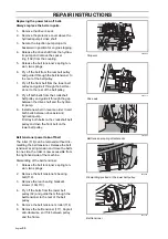
Replacing the articulated steering
bearings
1.
Remove the rear axle.
2.
Remove the steering cylinder’s rear
attachment.
3.
Remove the console and the steering
cylinder’s rear attachment (model year
06 and 07). Release the steering cylin-
der from the rear frame.
4.
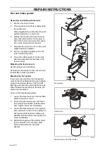
Remove the bolts (8) for the upper and
lower bearings in the rear frame.
5.
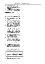
Lift the rear frame until the studs release
from the bearings and lift off the rear frame.
6.
Remove the circlips and knock out the
bearings.
Summary of Contents for PT 26D
Page 1: ...Workshop manual PT26D English ...
Page 13: ...English 12 SPECIAL TOOLS ...
Page 94: ...English 93 REPAIR INSTRUCTIONS 8043 197 Cutting unit Combi 155 ...
Page 107: ...English 106 REPAIR INSTRUCTIONS ...
Page 123: ...English 122 REPAIR INSTRUCTIONS ...
Page 145: ......
Page 146: ...English 145 APPENDIXES Circuit diagram Circuit diagram 1 ...
Page 147: ...English 146 APPENDIXES Circuit diagram 2 ...
Page 148: ...English 147 APPENDIXES Circuit diagram 3 ...
Page 149: ...English 148 APPENDIXES Circuit diagram 4 ...
Page 150: ...English 149 APPENDIXES Circuit diagram 5 ...
Page 151: ...English 150 APPENDIXES Circuit diagram 6 ...
Page 152: ...English 151 APPENDIXES Circuit diagram 7 ...
Page 153: ...English 152 APPENDIXES Circuit diagram 8 ...
Page 154: ...English 153 APPENDIXES Circuit diagram 9 ...
Page 155: ...English 154 APPENDIXES Circuit diagram 10 ...
Page 156: ...English 155 APPENDIXES Circuit diagram 11 ...
Page 157: ...English 156 APPENDIXES ...
Page 161: ...English 160 APPENDIXES 8043 160 Circuit board placement ...
Page 162: ...English 161 APPENDIXES Hydraulic diagram 8043 247 Hydraulic diagram ...
Page 163: ...English 162 APPENDIXES ...
Page 167: ...2009W18 115 08 30 26 ...


