English-
82
REPAIR INSTRUCTIONS
Replacing the solenoid clutch
1.
Remove the driver's seat and the fuel
tank.
2.
Remove the plate over the hydraulic
pump's drive axle.
3.
Ensure that the engine cannot start.
4.
Remove the bolts (101+106) to the front
clutch for the hydraulic pump's drive axle
and spacer ring (102).
5.
Remove the bolts (100) to the rear clutch
for the hydraulic pump's drive axle.
Remove the hydraulic pump's drive axle.
6.
Release the belt tensioner's spring ten-
sion and pry off the power take-off belts
from the upper pulley.
7.
Pull apart the connector for the solenoid
clutch’s power cable and cut the cable
tie for power cable.
8.
Remove the solenoid clutch’s centre
bolt (9). 8 mm hex key.
9.
Remove the front drive disc (96) for the
solenoid clutch.
10. Angle out the belt pulley unit so it runs
free and remove it from the solenoid
clutch.
11. Remove the clutch hub from the solenoid
clutch.
12. Pull forward the coil unit as far as possible.
13. Remove the three bolts for the rear drive.
They are screwed into the flywheel.
14. Pull forward the rear drive until it runs
free of the flywheel after which the sole-
noid clutch can be taken out downwards.
15. Remove the coil unit from the rear drive.
16. Guide the coil unit onto the rear drive
disc’s stub axle.
17. Assemble the rear drive disc with coil
unit on the engine's flywheel. Tightening
torque according to the table.
18. Move the coil unit backwards and make
sure that its lower cut-outs aligns in the
stop under the radiator. Check that there
is play between the cut-out and stop and
that the cable is routed to the left.
19. Assemble the clutch hub with the small
shoulder facing forwards and align in the
keyway on the rear drive disc.
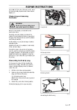
20. Assemble the belt pulley unit. Angle it
past the riveted plate and guide it onto
the clutch hub’s shoulder.
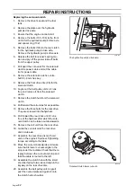
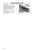
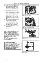
8043-164
The hydraulic pump's drive axle
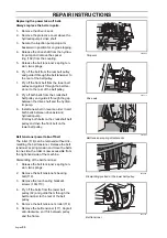
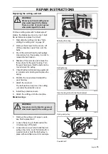
8043-212
Solenoid clutch lower cut-outs
Summary of Contents for PT 26D
Page 1: ...Workshop manual PT26D English ...
Page 13: ...English 12 SPECIAL TOOLS ...
Page 94: ...English 93 REPAIR INSTRUCTIONS 8043 197 Cutting unit Combi 155 ...
Page 107: ...English 106 REPAIR INSTRUCTIONS ...
Page 123: ...English 122 REPAIR INSTRUCTIONS ...
Page 145: ......
Page 146: ...English 145 APPENDIXES Circuit diagram Circuit diagram 1 ...
Page 147: ...English 146 APPENDIXES Circuit diagram 2 ...
Page 148: ...English 147 APPENDIXES Circuit diagram 3 ...
Page 149: ...English 148 APPENDIXES Circuit diagram 4 ...
Page 150: ...English 149 APPENDIXES Circuit diagram 5 ...
Page 151: ...English 150 APPENDIXES Circuit diagram 6 ...
Page 152: ...English 151 APPENDIXES Circuit diagram 7 ...
Page 153: ...English 152 APPENDIXES Circuit diagram 8 ...
Page 154: ...English 153 APPENDIXES Circuit diagram 9 ...
Page 155: ...English 154 APPENDIXES Circuit diagram 10 ...
Page 156: ...English 155 APPENDIXES Circuit diagram 11 ...
Page 157: ...English 156 APPENDIXES ...
Page 161: ...English 160 APPENDIXES 8043 160 Circuit board placement ...
Page 162: ...English 161 APPENDIXES Hydraulic diagram 8043 247 Hydraulic diagram ...
Page 163: ...English 162 APPENDIXES ...
Page 167: ...2009W18 115 08 30 26 ...


