English-
87
REPAIR INSTRUCTIONS
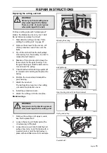
Cutting unit with suspension
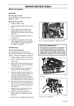
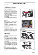
Cutting unit suspension, see figure on page 89.
Attaching and removing the cutting unit
See “Side shifting the cutting unit”. The
method also applies to Combi 132.
Side shifting the cutting unit
Cutting unit, Combi 155, can be side shifted
8 cm to the left or be centrally positioned on
the machine.
1.
Stop the engine. Switch off the weight
transfer switch.
.
2.
Remove the propeller shaft completely.
Pull the ring to release the quick connec-
tor and to be able to pull the propeller
shaft from the shaft journal.
3.
Start the engine and raise the cutting
unit to the transport position.
4.
Stop the engine.
5.
Remove the pins on both sides.
6.
Lower the cutting unit to the mowing
position.
When the engine has stopped: Ignition
switch in the ON position and the lever in
the lowered position within 3 seconds,
otherwise turn the ignition switch again.
7.
Remove the pins from the shafts and
remove the shafts from the link joints.
The cutting unit has now been removed
from the machine.
WARNING!
Prevent the engine from starting
when working on moving parts.
WARNING!
Exercise caution.
Risk of crush injuries
Wear protective gloves
WARNING!
Never leave the propeller shaft on
the machine with one end detached.
If the engine starts, damage might
occur.
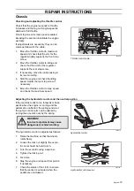
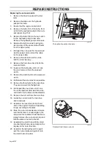
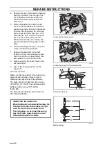
8009-762
Remove the propeller shaft
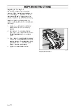
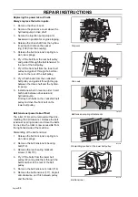
8043-050
Remove the pins
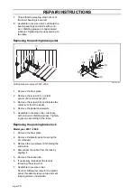
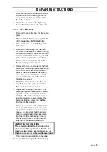
8009-776
Release the link joints
Summary of Contents for PT 26D
Page 1: ...Workshop manual PT26D English ...
Page 13: ...English 12 SPECIAL TOOLS ...
Page 94: ...English 93 REPAIR INSTRUCTIONS 8043 197 Cutting unit Combi 155 ...
Page 107: ...English 106 REPAIR INSTRUCTIONS ...
Page 123: ...English 122 REPAIR INSTRUCTIONS ...
Page 145: ......
Page 146: ...English 145 APPENDIXES Circuit diagram Circuit diagram 1 ...
Page 147: ...English 146 APPENDIXES Circuit diagram 2 ...
Page 148: ...English 147 APPENDIXES Circuit diagram 3 ...
Page 149: ...English 148 APPENDIXES Circuit diagram 4 ...
Page 150: ...English 149 APPENDIXES Circuit diagram 5 ...
Page 151: ...English 150 APPENDIXES Circuit diagram 6 ...
Page 152: ...English 151 APPENDIXES Circuit diagram 7 ...
Page 153: ...English 152 APPENDIXES Circuit diagram 8 ...
Page 154: ...English 153 APPENDIXES Circuit diagram 9 ...
Page 155: ...English 154 APPENDIXES Circuit diagram 10 ...
Page 156: ...English 155 APPENDIXES Circuit diagram 11 ...
Page 157: ...English 156 APPENDIXES ...
Page 161: ...English 160 APPENDIXES 8043 160 Circuit board placement ...
Page 162: ...English 161 APPENDIXES Hydraulic diagram 8043 247 Hydraulic diagram ...
Page 163: ...English 162 APPENDIXES ...
Page 167: ...2009W18 115 08 30 26 ...

