English-
96
REPAIR INSTRUCTIONS
4.
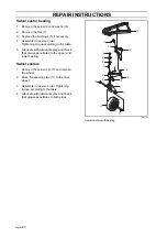
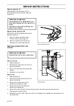
Remove the nuts, which hold the bearing
housing in position, from the top of the
cover. Make sure that the unit is posi-
tioned with the belt pulley against the
unit’s cover.
5.
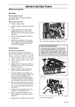
Place a wooden block under the unit
cover so that the blade is free from the
supporting surface. Knock on the screws
to remove the belt pulley. Do not knock
hard enough to deform the cover. If the
belt pulley is stuck, heat it with a hot air
gun. Try not to use a puller as it can
deform the belt pulley. Do not lose the
key that sits between the pulley and the
shaft.
6.
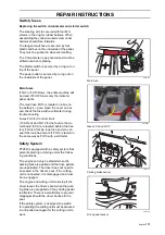
Place the bearing housing in a vice and
remove the blade and washers.
7.
Replace the blade bolt in the shaft.
Screw it in a few turns and tap or press
down the hub. Do not lose the key that
sits between the hub and the shaft.
8.
Mark one end of the shaft. Press or tap
out the shaft (2).
9.
Tap out the bearing and remove the
spacer (3).
Fit in reverse order.
Make sure that the shaft (2) is mounted in the
same direction as when it was removed,
otherwise the keys will not fit the grooves.
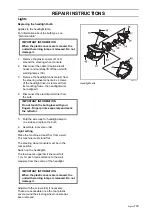
The blade bearing is tightened with a torque
of 20-25 Nm (14-18 lbft). The blade bearing is
tightened with a torque of 75-80 Nm
(52-56 lbft).
The belt pulley is tightened with a torque of
75-80 Nm (52-56 lbft).
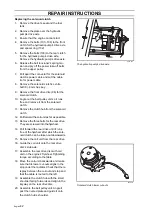
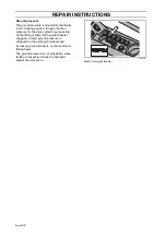
8043-179
Loosen the bearing housing
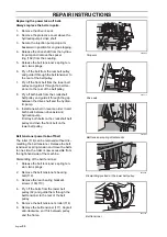
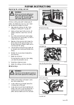
8043-180
Loosen the pulley. NOTE wooden block
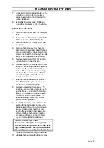
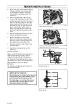
8009-295
Dismantling the hub
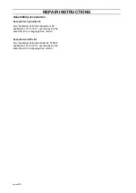
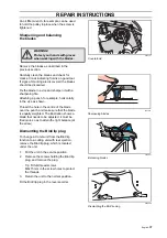
8043-181
Blade bearings
IMPORTANT INFORMATION
When tightening the blade shaft screws, the
transmission side should always be tight-
ened first and then the blade screws.
The belt pulley can be turned the wrong
way, the thicker side should be turned
downwards towards the blade.
Summary of Contents for PT 26D
Page 1: ...Workshop manual PT26D English ...
Page 13: ...English 12 SPECIAL TOOLS ...
Page 94: ...English 93 REPAIR INSTRUCTIONS 8043 197 Cutting unit Combi 155 ...
Page 107: ...English 106 REPAIR INSTRUCTIONS ...
Page 123: ...English 122 REPAIR INSTRUCTIONS ...
Page 145: ......
Page 146: ...English 145 APPENDIXES Circuit diagram Circuit diagram 1 ...
Page 147: ...English 146 APPENDIXES Circuit diagram 2 ...
Page 148: ...English 147 APPENDIXES Circuit diagram 3 ...
Page 149: ...English 148 APPENDIXES Circuit diagram 4 ...
Page 150: ...English 149 APPENDIXES Circuit diagram 5 ...
Page 151: ...English 150 APPENDIXES Circuit diagram 6 ...
Page 152: ...English 151 APPENDIXES Circuit diagram 7 ...
Page 153: ...English 152 APPENDIXES Circuit diagram 8 ...
Page 154: ...English 153 APPENDIXES Circuit diagram 9 ...
Page 155: ...English 154 APPENDIXES Circuit diagram 10 ...
Page 156: ...English 155 APPENDIXES Circuit diagram 11 ...
Page 157: ...English 156 APPENDIXES ...
Page 161: ...English 160 APPENDIXES 8043 160 Circuit board placement ...
Page 162: ...English 161 APPENDIXES Hydraulic diagram 8043 247 Hydraulic diagram ...
Page 163: ...English 162 APPENDIXES ...
Page 167: ...2009W18 115 08 30 26 ...

