English-
99
REPAIR INSTRUCTIONS
Electrical system
Generator
Checking the alternator
See Perkins Manual \ Electrical System \
Alternator – Test.
Replacing the alternator
1.
Release a battery cable.
2.
Release the power cables from the alter-
nator.
3.
Loosen the alternator fastening bolts
approximately one turn. Press in the
alternator and pry off the pump and alter-
nator belt.
4.
Remove the fastening bolts and lift off
the alternator.
5.
Assemble the alternator in the reverse
order. Adjust the belt tension according
to “Adjusting the pump and alternator
drive belts” on page 69.
Circuit board
Circuit board replacement
See “Connectors on the circuit card” on
page 158 and “Placement of circuit card con-
nections, melt fuses and LEDs” on page 157.
1.
Release a battery cable from the battery.
2.
Remove the panel with the cover under
switch panel.
3.
Mark up the cable harnesses under the
distribution box, so they are assembled
in the same position.
4.
Remove the plate, holding the rubber
grommets for the cable harnesses.
5.
Check the markings on the cable con-
nections. Some connections have mark-
ings on the cables. Supplement if
necessary when the connections have
been disconnected. All outlet sockets on
the circuit board are connection marked.
6.
Disconnect all connections from the cir-
cuit card. Use bent round nosed pliers to
press in the plastic catches holding the
connections.
7.
Release the cable harnesses from the
underside of the distribution box.
8.
Remove the two front switches. Four
plastic catches on each switch must be
pressed in.
9.
Remove the nuts, holding the circuit board.
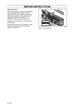
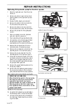
8009-781
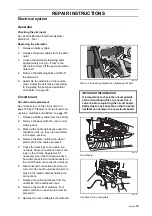
Press on the bearing shield when tightening the belt.
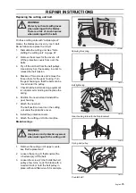
8043-140
Circuit board
IMPORTANT INFORMATION
It is important to check the circuit outside
of the circuit board first, to ensure this is
correct, before replacing the circuit board.
Partly due to cost, but also so that no exter-
nal fault can damage the new circuit board.
8043-141
Use bent round nosed pliers
Summary of Contents for PT 26D
Page 1: ...Workshop manual PT26D English ...
Page 13: ...English 12 SPECIAL TOOLS ...
Page 94: ...English 93 REPAIR INSTRUCTIONS 8043 197 Cutting unit Combi 155 ...
Page 107: ...English 106 REPAIR INSTRUCTIONS ...
Page 123: ...English 122 REPAIR INSTRUCTIONS ...
Page 145: ......
Page 146: ...English 145 APPENDIXES Circuit diagram Circuit diagram 1 ...
Page 147: ...English 146 APPENDIXES Circuit diagram 2 ...
Page 148: ...English 147 APPENDIXES Circuit diagram 3 ...
Page 149: ...English 148 APPENDIXES Circuit diagram 4 ...
Page 150: ...English 149 APPENDIXES Circuit diagram 5 ...
Page 151: ...English 150 APPENDIXES Circuit diagram 6 ...
Page 152: ...English 151 APPENDIXES Circuit diagram 7 ...
Page 153: ...English 152 APPENDIXES Circuit diagram 8 ...
Page 154: ...English 153 APPENDIXES Circuit diagram 9 ...
Page 155: ...English 154 APPENDIXES Circuit diagram 10 ...
Page 156: ...English 155 APPENDIXES Circuit diagram 11 ...
Page 157: ...English 156 APPENDIXES ...
Page 161: ...English 160 APPENDIXES 8043 160 Circuit board placement ...
Page 162: ...English 161 APPENDIXES Hydraulic diagram 8043 247 Hydraulic diagram ...
Page 163: ...English 162 APPENDIXES ...
Page 167: ...2009W18 115 08 30 26 ...

