English-
125
TROUBLE SHOOTING
Voltage measurement
If the engine does not run, there is only
voltage to the solenoid valves for
approximately 3 seconds after the ignition
has been switched to the ON position. This
limitation can be bypassed by disconnecting
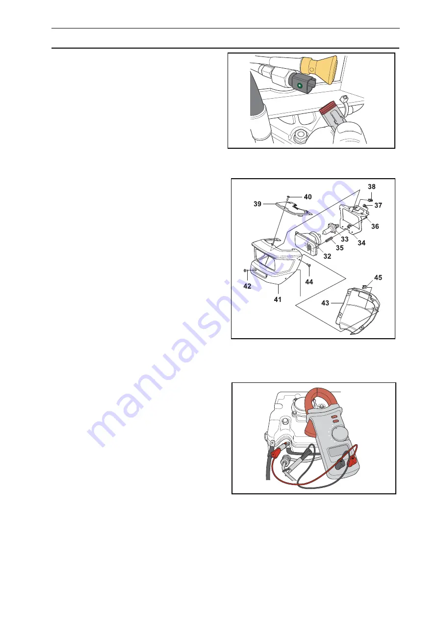
the connector from the engine's oil pressure
switch. Do not forget to replace the connector
after measuring.
Lights
The lighting circuits' weakest point is the bulbs
(consumable material). First action is always
to check whether the bulb has blown. If the
bulb is okay, continue trouble shooting in the
same way as for the solenoid valves above.
Glow plug heating and starter motor
Conditions for glow plug heating and starter
motor circuit:
•
The parking brake is on.
•
The hydraulic pump for the drive system
is in the 0-position.
Check this with the LEDs in the sensors.
The circuits for glow plug heating and the
starter motor as well as the cooling fan’s soft
start function do not have a red LED. Trouble
shooting these circuits can therefore be
slightly different. If, for example, there is a
short circuit in the circuit for glow plug heating,
the green LED will not come on. Disconnect
the cable from the front glow plug. Refit the nut
so that the rail makes good contact for future
measurements. If the green LED now comes
on when glow plug heating is activated this
indicates the glow plug is short circuited.
Check with an ohmmeter, the value between
the front glow plug with the rail connected (all
three glow plugs) and the engine block it
should be approximately 0.3-0.4
If this
value is not correct, disconnect and measure
each glow plug individually, set value 1-1.3
.
Now disconnect the connector from the circuit
board and if the green LED comes on for glow
plug heating, the cable harnesses short-
circuited. Note that the cable harness has
three wires for the glow plug heating function
to manage the high current (40 A with a cold
plug) to the glow plug without losses.
The open circuit is not indicated as the red LED is missing, but you can find the broken cable by measuring
with an ohmmeter between the pins. If the green LED does not come on, disconnect the connector to the
switch from the circuit board and measuring the resistance on the switch with cables before replacing the
circuit board.
8043-176
Disconnecting oil pressure contact
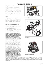
8043-130
Headlight parts
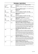
8043-178
Resistance test all glow plugs
Summary of Contents for PT 26D
Page 1: ...Workshop manual PT26D English ...
Page 13: ...English 12 SPECIAL TOOLS ...
Page 94: ...English 93 REPAIR INSTRUCTIONS 8043 197 Cutting unit Combi 155 ...
Page 107: ...English 106 REPAIR INSTRUCTIONS ...
Page 123: ...English 122 REPAIR INSTRUCTIONS ...
Page 145: ......
Page 146: ...English 145 APPENDIXES Circuit diagram Circuit diagram 1 ...
Page 147: ...English 146 APPENDIXES Circuit diagram 2 ...
Page 148: ...English 147 APPENDIXES Circuit diagram 3 ...
Page 149: ...English 148 APPENDIXES Circuit diagram 4 ...
Page 150: ...English 149 APPENDIXES Circuit diagram 5 ...
Page 151: ...English 150 APPENDIXES Circuit diagram 6 ...
Page 152: ...English 151 APPENDIXES Circuit diagram 7 ...
Page 153: ...English 152 APPENDIXES Circuit diagram 8 ...
Page 154: ...English 153 APPENDIXES Circuit diagram 9 ...
Page 155: ...English 154 APPENDIXES Circuit diagram 10 ...
Page 156: ...English 155 APPENDIXES Circuit diagram 11 ...
Page 157: ...English 156 APPENDIXES ...
Page 161: ...English 160 APPENDIXES 8043 160 Circuit board placement ...
Page 162: ...English 161 APPENDIXES Hydraulic diagram 8043 247 Hydraulic diagram ...
Page 163: ...English 162 APPENDIXES ...
Page 167: ...2009W18 115 08 30 26 ...


