English-
126
TROUBLE SHOOTING
A breakage on the cable between J1 and the
analogue sensor on the thermostat housing
results in theemergency glow plug heating
function activating with a fixed heating time.
Caution: only with an open circuit, if there is
another fault on the sensor so that glow plug
heating does not work the connector can be
disconnected from the sensor and run with
this emergency glow plug heating time. The
time is temperature independent and about
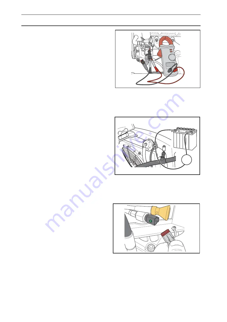
half of the max. time. Check the sensor with
an ohmmeter 0.9 - 1
at room temperature.
With regard to the circuit that activates the
starter motor, proceed in the same way as for
the glow plug heating circuit. A fault in the
glow plug heating circuit can prevent the
starter motor from working. Turn the ignition
key back to glow plug heating and the start
position within 3 seconds. If the starter motor
works, look for the fault in the glow plug heat-
ing circuit.
Cooling fan
A fault in the circuit to the cooling fan's soft
start function can mean that the fan does not
start. Check the cables between the circuit
board and connector on the fan for a short
circuit or open circuit. Now connect an exter-
nal battery to the connector and test run the
fan. Measure the current with an ammeter. If
the fan works normally and the current after
start does not exceed 12 A, replace the cir-
cuit board.
Oil pressure
A short circuited oil pressure sensor means
the engine will stop directly after starting. Dis-
connect the cable from the sensor and test
start. If the engine now starts it is either the
sensor that is malfunctioning or the oil pres-
sure is too low. A sensor with an internal
mechanical fault can cause engine problems,
the engine can stop or run unevenly.
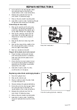
8043-177
Resistance test analogue sensor
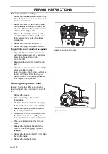
A
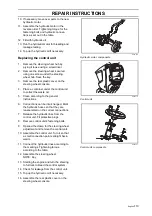
8043-183
Measuring current to cooling fan
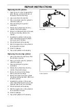
8043-176
Disconnecting oil pressure contact
Summary of Contents for PT 26D
Page 1: ...Workshop manual PT26D English ...
Page 13: ...English 12 SPECIAL TOOLS ...
Page 94: ...English 93 REPAIR INSTRUCTIONS 8043 197 Cutting unit Combi 155 ...
Page 107: ...English 106 REPAIR INSTRUCTIONS ...
Page 123: ...English 122 REPAIR INSTRUCTIONS ...
Page 145: ......
Page 146: ...English 145 APPENDIXES Circuit diagram Circuit diagram 1 ...
Page 147: ...English 146 APPENDIXES Circuit diagram 2 ...
Page 148: ...English 147 APPENDIXES Circuit diagram 3 ...
Page 149: ...English 148 APPENDIXES Circuit diagram 4 ...
Page 150: ...English 149 APPENDIXES Circuit diagram 5 ...
Page 151: ...English 150 APPENDIXES Circuit diagram 6 ...
Page 152: ...English 151 APPENDIXES Circuit diagram 7 ...
Page 153: ...English 152 APPENDIXES Circuit diagram 8 ...
Page 154: ...English 153 APPENDIXES Circuit diagram 9 ...
Page 155: ...English 154 APPENDIXES Circuit diagram 10 ...
Page 156: ...English 155 APPENDIXES Circuit diagram 11 ...
Page 157: ...English 156 APPENDIXES ...
Page 161: ...English 160 APPENDIXES 8043 160 Circuit board placement ...
Page 162: ...English 161 APPENDIXES Hydraulic diagram 8043 247 Hydraulic diagram ...
Page 163: ...English 162 APPENDIXES ...
Page 167: ...2009W18 115 08 30 26 ...

