English-
44
DESIGN AND FUNCTION
General
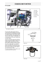
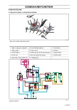
The machine has two hydraulic pumps with a
common hydraulic tank. The pump for work-
ing hydraulics (8) is driven from the engine's
timing gear and supplies system compo-
nents, which require hydraulic pressure irre-
spective of whether the machine is driven or
stationary. The pump is a gearwheel-pump. It
also supplies the drive system pump with
feed pressure 1.8 MPa (18 bar).
The hydraulic pump for the drive system (9)
is driven by an axle with two flexible clutches
from the engine's flywheel. It is an axial pis-
ton pump, that has a pivot box. By setting the
pivot box, the pump can be controlled to give
a variable flow with different directions. You
can then adjust the speed and drive forwards
or reverse. The pivot box is controlled by a
mechanical linkage from the drive pedals.
The hydraulic motors (7), one for each wheel,
are inverted gear motors. The displacement
of the pumps is different for forwards and
reverse. Even though the motors work in both
directions of rotation they are marked CV
clockwise), depending on the inner clutch.
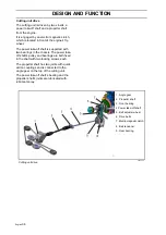
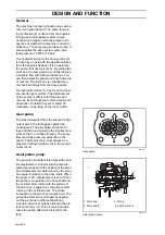
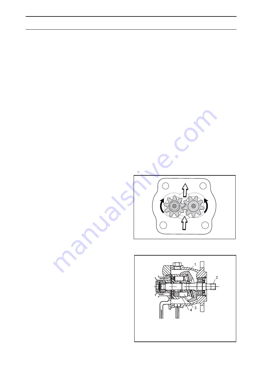
Gear pump
The oil is transported from the inlet port to the
output port in the tooth gaps against the
housing wall. The play between the tooth
tops and the housing wall is the smallest pos-
sible so that no oil leaks through. The pump
flow (and thus pressure) depends on the
speed. That’s why there must always be a
pressure limiting overflow vent in the pump’s
outlet circuit.
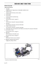
Axial piston pump
The pump is of annular piston type with varia-
ble displacement. Annular piston pump dis-
placement varies with the position of the pivot
box. Displacement is determined by the pivot
box angle in relation to the drive shaft. When
the angle is 90°, displacement is zero. When
the pump is in operation, the drive shaft and
the cylinder drum rotate with the pistons. If
the pivot box is angled out, the pistons start
running in the cylinder drum. The stroke
increases as the pivot box is angled out. The
pump flow direction is changed by angling
out the pivot box to different directions.
A certain amount of oil leaks through the pis-
tons when they run. This oil cools and lubri-
cates the pump, after which it is led to the
tank.
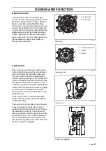
8043-173
Gear pump
8043-239
Axial piston pump
1. Pivot box
3. Piston
2. Drive shaft
4. Cylinder drum
Summary of Contents for PT 26D
Page 1: ...Workshop manual PT26D English ...
Page 13: ...English 12 SPECIAL TOOLS ...
Page 94: ...English 93 REPAIR INSTRUCTIONS 8043 197 Cutting unit Combi 155 ...
Page 107: ...English 106 REPAIR INSTRUCTIONS ...
Page 123: ...English 122 REPAIR INSTRUCTIONS ...
Page 145: ......
Page 146: ...English 145 APPENDIXES Circuit diagram Circuit diagram 1 ...
Page 147: ...English 146 APPENDIXES Circuit diagram 2 ...
Page 148: ...English 147 APPENDIXES Circuit diagram 3 ...
Page 149: ...English 148 APPENDIXES Circuit diagram 4 ...
Page 150: ...English 149 APPENDIXES Circuit diagram 5 ...
Page 151: ...English 150 APPENDIXES Circuit diagram 6 ...
Page 152: ...English 151 APPENDIXES Circuit diagram 7 ...
Page 153: ...English 152 APPENDIXES Circuit diagram 8 ...
Page 154: ...English 153 APPENDIXES Circuit diagram 9 ...
Page 155: ...English 154 APPENDIXES Circuit diagram 10 ...
Page 156: ...English 155 APPENDIXES Circuit diagram 11 ...
Page 157: ...English 156 APPENDIXES ...
Page 161: ...English 160 APPENDIXES 8043 160 Circuit board placement ...
Page 162: ...English 161 APPENDIXES Hydraulic diagram 8043 247 Hydraulic diagram ...
Page 163: ...English 162 APPENDIXES ...
Page 167: ...2009W18 115 08 30 26 ...


