English-
45
DESIGN AND FUNCTION
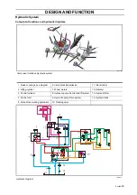
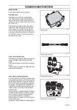
Hydraulic motor
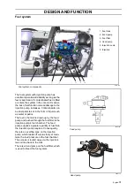
The hydraulic motor is an inverted gear
motor. The valve disc and gearwheel unit are
located on two levels in the motor. Between
these is a partition wall with drilled holes,
where the oil can flow when they are not cov-
ered by the oscillating rotor. When driving in
one direction, the incoming oil is piped to the
gearwheel unit, which is provided a certain
rotation and power by the oil, via the valve
disc’s outer track. The oil is then piped back
via the valve disc and its inner track out
through the output port.
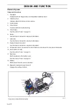
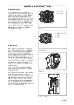
Control unit
The control unit consists of a rotating valve
and a rotating oil gauge. When the operator
turns the wheels, the hydraulic oil is piped
from the control unit via the rotating valve
and the rotating oil gauge to the cylinder port
L(Left) or R(Right), depending on which way
the operator turns the steering wheel. The
rotating oil gauge measures the oil flow to the
control unit in proportion to the steering angle
on the wheels. It is possible to steer the
machine even if there is a breakdown in the
hydraulic pump.
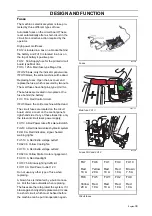
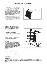
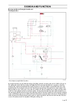
In the control unit is an excess flow valve,
which limits the system pressure to approx.
12 MPa (120 bar).
The control unit, which has a type of excess
pressure function, provides the option in
neutral to let the flow go from port P through
the unit and on to port E. The control unit
always prioritises control function and in case
of excess pressure, the control unit permits
the oil to be piped to port E. At full lock all
flow is led through the excess flow valve and
the flow to port E is stopped.
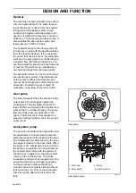
8043-211
Valve disc
1. Outer track
2. Inner track
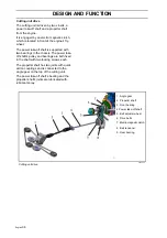
8043-210
Gearwheel unit
3. Hole to valve disc
4. Roller
5. Rotor
8043-116
Control unit
8043-237
Control unit, diagram
Summary of Contents for PT 26D
Page 1: ...Workshop manual PT26D English ...
Page 13: ...English 12 SPECIAL TOOLS ...
Page 94: ...English 93 REPAIR INSTRUCTIONS 8043 197 Cutting unit Combi 155 ...
Page 107: ...English 106 REPAIR INSTRUCTIONS ...
Page 123: ...English 122 REPAIR INSTRUCTIONS ...
Page 145: ......
Page 146: ...English 145 APPENDIXES Circuit diagram Circuit diagram 1 ...
Page 147: ...English 146 APPENDIXES Circuit diagram 2 ...
Page 148: ...English 147 APPENDIXES Circuit diagram 3 ...
Page 149: ...English 148 APPENDIXES Circuit diagram 4 ...
Page 150: ...English 149 APPENDIXES Circuit diagram 5 ...
Page 151: ...English 150 APPENDIXES Circuit diagram 6 ...
Page 152: ...English 151 APPENDIXES Circuit diagram 7 ...
Page 153: ...English 152 APPENDIXES Circuit diagram 8 ...
Page 154: ...English 153 APPENDIXES Circuit diagram 9 ...
Page 155: ...English 154 APPENDIXES Circuit diagram 10 ...
Page 156: ...English 155 APPENDIXES Circuit diagram 11 ...
Page 157: ...English 156 APPENDIXES ...
Page 161: ...English 160 APPENDIXES 8043 160 Circuit board placement ...
Page 162: ...English 161 APPENDIXES Hydraulic diagram 8043 247 Hydraulic diagram ...
Page 163: ...English 162 APPENDIXES ...
Page 167: ...2009W18 115 08 30 26 ...

