English-
46
DESIGN AND FUNCTION
Radiator
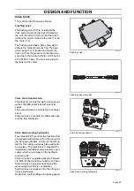
Hydraulic cooler, which is located at the front
of the engine, is common with the radiator for
the engine’s cooling system. The left-hand
side of the radiator (2) acts as the hydraulic
cooler and the right-hand side (1) as the cool-
ing system’s radiator. The radiator is made of
aluminium to withstand high pressure, thus
repairs are not recommended.
The radiator is cooled by an electrically driven
thermostat controlled cooling fan, located in
the engine compartment. In front of the radia-
tor is a grille, which can be easily dismantled
to remove grass clippings or the like.
Hydraulic filter
The hydraulic filters are located in the
hydraulic tank and must be cleaned and
replaced regularly as set out in “Service
Schedule” on page 19.
Used hydraulic filters are to be handled as
environmentally hazardous waste.
Filler screen
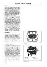
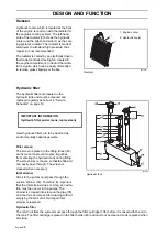
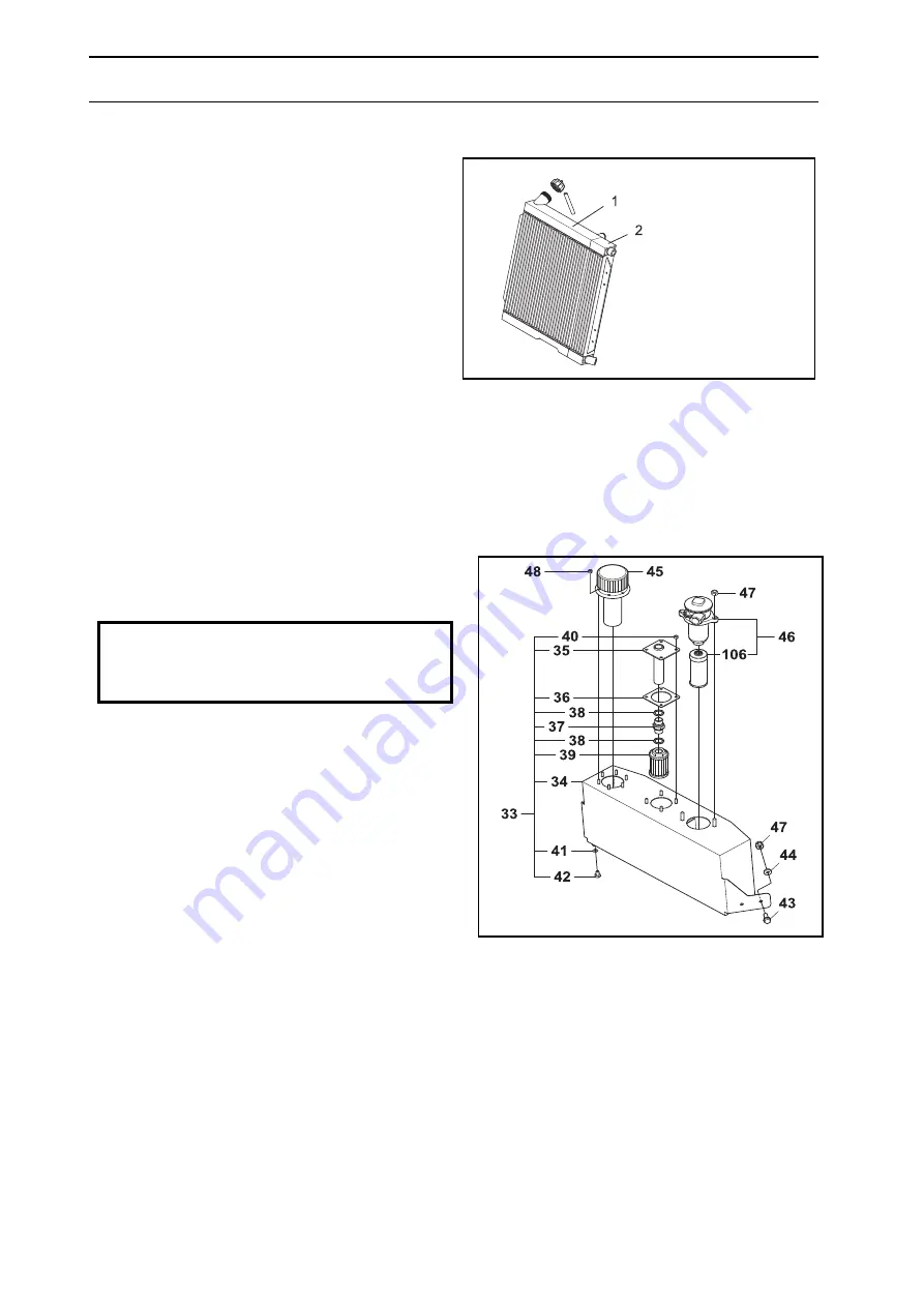
The screen is placed in the filling funnel (45)
and is meant to prevent coarse impurities
from entering the hydraulic tank during filling.
The screen size is chosen so that the filled oil
can easily pass through. The screen is
cleaned when necessary.
Inlet strainer
All oil to the pumps must pass through the
suction strainer (39). Therefore it’s important
that the inlet strainer does not clog, as cavita-
tion may then occur in the pumps. The
strainer is screwed into place on the pipe (35)
and can thus be removed for cleaning without
emptying the tank of oil. Damaged inlet
strainer is replaced.
Hydraulic filter
The return oil from the system must pass through the filter cartridge (106) before it is mixed with the oil in
the tank. The filter cartridge is placed in the filter holder (46) and must not be cleaned but is replaced when
servicing.
8043-226
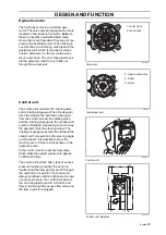
Radiator
1. Engine cooler
2. Hydraulic cooler
IMPORTANT INFORMATION
Hydraulic filter and screens, replacement
8043-122
Hydraulic tank
Summary of Contents for PT 26D
Page 1: ...Workshop manual PT26D English ...
Page 13: ...English 12 SPECIAL TOOLS ...
Page 94: ...English 93 REPAIR INSTRUCTIONS 8043 197 Cutting unit Combi 155 ...
Page 107: ...English 106 REPAIR INSTRUCTIONS ...
Page 123: ...English 122 REPAIR INSTRUCTIONS ...
Page 145: ......
Page 146: ...English 145 APPENDIXES Circuit diagram Circuit diagram 1 ...
Page 147: ...English 146 APPENDIXES Circuit diagram 2 ...
Page 148: ...English 147 APPENDIXES Circuit diagram 3 ...
Page 149: ...English 148 APPENDIXES Circuit diagram 4 ...
Page 150: ...English 149 APPENDIXES Circuit diagram 5 ...
Page 151: ...English 150 APPENDIXES Circuit diagram 6 ...
Page 152: ...English 151 APPENDIXES Circuit diagram 7 ...
Page 153: ...English 152 APPENDIXES Circuit diagram 8 ...
Page 154: ...English 153 APPENDIXES Circuit diagram 9 ...
Page 155: ...English 154 APPENDIXES Circuit diagram 10 ...
Page 156: ...English 155 APPENDIXES Circuit diagram 11 ...
Page 157: ...English 156 APPENDIXES ...
Page 161: ...English 160 APPENDIXES 8043 160 Circuit board placement ...
Page 162: ...English 161 APPENDIXES Hydraulic diagram 8043 247 Hydraulic diagram ...
Page 163: ...English 162 APPENDIXES ...
Page 167: ...2009W18 115 08 30 26 ...


