background image

English-4

LEDGER OF CHANGES

Ledger of changes

Enter changes and corrections in the workshop manual into the table below. Changes can be reported by 
Husqvarna AB as a service message or equivalent. 


Date

Page

Revision

Signature

Summary of Contents for PT 26D

Page 1: ...Workshop manual PT26D English ...

Page 2: ... with suspension 58 Repair Instructions 61 Removing and refitting the engine 61 Cooling system 64 Lubrication system 67 Auxiliary system 69 Fuel and intake system 70 Chassis 73 Steering console 75 Dismantling the rear axle 76 Assembling the rear axle 77 Replacing bushings for pendulum shaft 77 Replacing the articulated steering bearings 77 Replacing the parking brake pedal 78 Replacing the parking...

Page 3: ...c motor 118 Replacing the control unit 119 Replacing the lift cylinder 120 Replacing the steering cylinder 120 Hydraulic pressure for weight transfer 121 Replacing the solenoid valve 121 Trouble shooting 123 General 123 Engine with accessories 123 Electrical System 124 Hydraulic System 131 Fuel system 136 Trouble Shooting Guide 136 Circuit diagram 145 Circuit board 157 Hydraulic diagram 161 Index ...

Page 4: ...ractor components we refer to the manual published by the respective subcontractor See Engine on page 28 and System components Manuals on page 48 We recommend acquiring these manuals to obtain fully comprehensive service documentation for the machine The book is made up of the following chapters Safety instructions a selection which is important when carrying out service on the machine Additional ...

Page 5: ...EDGER OF CHANGES Ledger of changes Enter changes and corrections in the workshop manual into the table below Changes can be reported by Husqvarna AB as a service message or equivalent Date Page Revision Signature ...

Page 6: ...ardous One litre of diesel fuel can destroy up to 1 million litres of drinking water Diesel is less flammable than petrol at normal temperatures but becomes very combustible if heated to the flash point This varies depending on the type of diesel but is normally higher than 50ºC 120ºF When using compressed air do not direct the jet towards the body Air can penetrate into the blood circula tion sys...

Page 7: ... skin can cause serious corrosive injuries In the event of spillage on the skin wash immediately with water Acid in the eyes can cause blindness contact a doctor immediately Be careful when servicing the battery Explosive gases form in the battery Never perform maintenance on the battery while smoking or in the vicinity of open flames or sparks This can cause the battery to explode and cause serio...

Page 8: ... connect it last Exercise care with tools so that short circuiting does not occur Do not short circuit across the starter relay s connections to run the starter motor Engine repairs Immediately consult a doctor if the skin comes into contact with fuel which is under high pressure The combustible material in some of the engine s components e g certain seals can be very dangerous if ignited Never al...

Page 9: ...ny spillage without it penetrating into the ground Avoid spillage use a funnel and fill up carefully When draining ensure that a suitably sized container is placed correctly Remember that the oil does not always run straight down Transfer the waste oil into a sealed container and hand in for destruction Remember to follow local regulations Generally you can deposit waste oil at workshops or petrol...

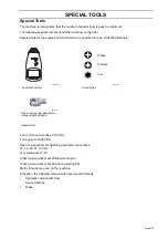
Page 10: ...nch 200 Nm Open ring spanners for tightening hydraulic connections 17 19 22 27 32 mm Torx screwdriver T 25 Cross tip screwdriver set Phillips marking P Cross tip screwdriver set Pozidrive markingPZ Metric threads are used on the machine Exception the following components have imperial threads Hydraulic components from Sauer Danfoss Brake Special tools RPM TOT MEM DIGITAL TACHOMETER 8009 853 Laser ...

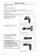
Page 11: ...ometer connection Intermediate coupling thread M14x1 5 For measuring point P2 9 16 JIC for T pipe and M16x2 for manometer connection For measuring point P3 P4 P5 Q2 9 16 UNF 18 in flushing valve and M16x2 DKLO for manometer connection Intermediate coupling thread M14x1 5 For measuring point Q1 9 16 JIC and steel plug 9 16 JIC inner thread 8043 240 Nipples for measuring point P1 8043 241 Nipples fo...

Page 12: ...eflective tape The display will come on after 1 2 seconds 4 Hold the measurement button down during the entire measurement The instrument switches off when the meas urement button is released Read the last highest and lowest values The instrument automatically saves the last highest and lowest measurement values during a measurement i e as long as the measurement button is held down Press and hold...

Page 13: ...English 12 SPECIAL TOOLS ...

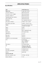
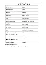
Page 14: ...ine Precombustion chamber diesel 3 cylinder in line engine Brand Perkins Model 403C 11 Power 26 19 7 hp kW 3000 rpm Max torque 67 Nm 2100 rpm Displacement 1131 cm3 Idle speed 1650 rpm Max speed 3000 rpm Conforms to environment standard EG stage 2 and EPA Tier 2 Fuel min 45 Cetane 2 0 4 5 cSt 40 C 0 835 0 855 kg l Sulphur 0 2 w Tank volume 37 5 liters 9 9 US Gal Oil Viscosity see table under Changi...

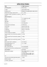
Page 15: ... V H4 Solenoid clutch coil resistance 2 Ohm Solenoid valve 30 W coil resistance guideline value 4 8 Ohm Solenoid valve 26 W coil resistance guideline value 5 7Ohm Solenoid valve 20 W coil resistance guideline value 7 5 Ohm Main power relay coil resistance 19 5 20 Ohm Glow plug resistance 1 pc 1 0 1 3 Ohm Hydraulic System Max working pressure 210 bar 3050 PSI Power steering circuit max working pres...

Page 16: ... 113 kg 248 lb Length machine with unit approximately 2 900 mm 9 52 ft Cutting unit Combi 132 Cutting width 1 320 mm 52 Cutting heights 25 4 127 mm 1 5 Blade length 560 mm 22 490 mm 19 3 Width 1 340 mm 52 8 Weight approximately 100 kg 13 29kg Length machine with unit approximately 2 900 mm 290 17 cm approximately 2 730 mm 273 10 cm Noise emissions with unit C155 Measured noise level 104 dB A Guara...

Page 17: ... M10 47 Nm 17 mm M10 12 9 70 Nm Drive disc on flywheel 18 19 mm 10 mm M12 81 Nm 30 mm M20 200 Nm Lift bolt Hydraulic hoses coupling nuts T pipe 5 Counterhold required Spanner size Thread Tightening Torques Note 17 mm 9 16 ORFS 15 Nm Control unit 19 mm 9 16 JIC 35 Nm 22 mm 3 4 JIC 60 Nm 22 mm 9 16 ORFS 25 Nm Control unit 27 mm 7 8 JIC 85 Nm Hydraulic connecting nipples in material 5 Spanner size Th...

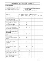
Page 18: ...he hydraulic oil filter Change the engine oil and filter Check the tension and condition of the belts generator and water pump belt power take off belts cutting unit belt Check the muffler screws and the wheel nuts Check the muffler screws and wheel nuts Check the hoses and couplings as well as oil and fluid levels Check for any leakage of water and oil Adjust the cutting unit so that its rear edg...

Page 19: ...ons according to the Perkins workshop manual Replace the cooler fluid Adjust the valves and check the engine speed Replace the alternator and water pump belt 2000 hour service 1 Perform the 1 000 hour service 2 Below are service actions according to the Perkins workshop manual Replace the crankcase ventilation diaphragm Check the starter Check the engine mountings Check the alternator 3000 hour ser...

Page 20: ...every refuelling 67 Check the hydraulic oil level 109 Check the coolant level 29 Check clean the engine s radiator air intake the radiator screen and radiators 65 Check fastenings screws nuts etc Start the engine and blades listen for unusual sounds Clean under the cutting unit and belt covers Check for damage Check the air pressure in the tyres 100 kPa 91 Clean thoroughly around the engine Clean ...

Page 21: ...ake off belts and cutting unit belt 84 95 Check the condition of the hydraulic hoses Replace fuel filter and check hoses4 Adjust the valves and check the engine speed4 Replace the pump and alternator belt 69 Change the hydraulic oil and filter1 4 111 Change the oil in the bevel gear 94 Change the cooling liquid4 30 Check all hoses with connections to the engine and the engine s mountings Replace t...

Page 22: ...kly 4 Performed by authorised service workshop Described in this workshop manual Not described in this workshop manual or the operator s manual Described in the operator s manual WARNING No service operations may be performed on the engine or cutting unit unless The engine is stopped The parking brake is on The ignition key has been removed The cutting unit is disengaged ...

Page 23: ...lations Manoeuvre controls Checking oil levels Topping up oil and the type of oil required First oil change after the running in period The need and benefit of following the service schedule and leaving the machine for regular service Which fuel is to be used Mowing tips to attain good results Application areas for mulching The accessories available for the customer s type of machine Guarantee rul...

Page 24: ...ount of diesel fuel Bleed the fuel system See instructions under Repair instructions Fuel and intake system 8 Checking neutral Check that the drive pedals spring back to neutral position when they are unactuated Check with LEDs on the sensor by the pump s operating lever 9 Test Running Listen for abnormal noises and check that all func tions works as intended Run the engine until operating tempera...

Page 25: ...torque The tightening toque should be about 20 Nm 12 Checking for leakage After test running check that no leakage of cool ant engine or hydraulic oil occurs 13 Customer info on delivery See Delivery Procedures on page 22 14 Administration Fill in the sales papers customer register etc Don t forget to fill in the serial number on page 5 in the Operator s manual and to confirm that the delivery ser...

Page 26: ...e The muffler is equipped with an integrated catalytic converter for exhaust emission con trol 8009 757 Husqvarna PT 26D 8043 030 Catalytic converter Husqvarna PT 26D is prepared for the permanent installation of the following accessories Traffic kit Lighting with direction indicators posi tion light and rotating warning lamp Tool attachment hydraulic valves quick action couplings hydraulic hoses ...

Page 27: ...on to the machine Combi 132 can only be mounted centrally The cutting unit is driven by two v belts a power take off shaft and a propeller shaft from the engine It is engaged by an electro magnetic clutch which is located in front of the engine s flywheel If necessary the cutting unit can be turned to the service position to be able to clean the underneath of the cover for example 8009 892 Combi 1...

Page 28: ...ated on the engine block above the injection pump Please state these when ordering spare parts The hydraulic pump and hydraulic motors are equipped with rating plates stating the type designation and serial or manufacturing number Please state these when ordering spare parts Pt26 D 965 08 04 01 s n 06 2400002 Husqvarna AB Husqvarna SWEDEN 8043 101 The machine s serial number 8043 102 The engine s ...

Page 29: ...pairing the engine The man ual is common for 2 3 and 4 cylinder engines RENR9825 is the publication number of the English version of Perkins Service Manual 400C Series The manual may be available in other languages but not Swedish Check at www Perkins com or with the Perkins service organisation It is important that only original spare parts are used to repair the engine If other parts are used th...

Page 30: ...The radiator is cooled by an electrically driven thermostat controlled cooling fan located in the engine compartment In front of the radiator is a grille which can be easily dismantled to remove grass clippings or the like The cooling system is drained using two plugs one located on the engine block and the other on the lower radiator hose When draining the cooling system both the taps must be ope...

Page 31: ...a glycol based antifreeze that is approved by the applicable norms BS 6580 1992 or ASTMD 3306 89 or AS 2108 1977 indicated on the packaging The antifreeze agent must be intended for use with light alloy engines and contain addi tives that protect the engine s cooling system against corrosion IMPORTANT INFORMATION Never fill a hot engine with cold coolant Risk of extensive engine damage Mixing tabl...

Page 32: ...y the feed pump and pushed through the fuel filter to the injection pump s fuel chamber The feed pump supplies a greater quantity of fuel than the injection pump requires Consequently there is an overflow pipe on the injection pump which leads off surplus fuel yet main tains the feed pressure in the fuel chamber The excess is routed away via the injector s leak oil line back to the tank There is a...

Page 33: ...is adjusted by a pressure limiting valve in the control unit 4 under the steering wheel The control unit 4 is connected directly to the steering wheel and runs the steering cylinder 3 which is connected between the chassis and the rear axle in and out If the engine stops it is still possible to steer but the wheel is heavy to turn The hydraulic tank 14 supplies all hydraulic functions on the machi...

Page 34: ...ck for the transmission 6 has solenoid valves for the differential lock and high low gears The block leads the oil to the four hydraulic motors 7 that drive each wheel Tank 14 and filtering 11 13 are common to the whole hydraulic system Also see chapter Hydraulic System on page 43 Differential Lock The machine is equipped with an electro hydraulic differential lock which is controlled by a pedal s...

Page 35: ... power take off shaft s pulley and bearings are both fixed in the shaft with two locking screws each The propeller shaft has two joints with quick action couplings and is connected to the angle gear on the top of the cutting unit The power take off shaft s bearing and the propeller shaft s joints are lubricated with lubricant spray 8043 185 Cutting unit drive 1 Angle gear 2 Propeller shaft 3 Front...

Page 36: ...required in order for the pedal not to be rigid in which case the parking brake lock would not work The parking brake lock is located in front of the pedal s bearing It distinguishes between the model years Model year 2006 has a spring loaded bell crank whose lower part locks the pedal The upper part protrudes from under the seat cushion and is used for releasing the parking brake Beginning with m...

Page 37: ... component information 7 Alternator See the Perkins manual for component information 8 Engine temperature sensor See the Perkins manual for component information 9 Oil pressure sensor concealed See the Perkins service manual for component information 10 Fuses and main relay See the section Fuses on page 39 11 Main fuse Melt fuse placed on the battery pole See the section Fuses on page 39 12 Batter...

Page 38: ...example of a circuit solution the circuit for the power take off solenoid clutch is described The power take off shaft and thus the cutting unit is engaged with the switch for driving the cutting unit PTO switch See Circuit diagram 8 on page 152 If no interlockings are active the circuit board transmits an output signal supplies power to the solenoid clutch PTO clutch see Circuit diagram 4 on page...

Page 39: ...o the consumer load The circuit board has apart from components for signal processing circuit fuses and BITE built in test equipment in the form of green and red LEDs See Built in test equipment on page 41 Some circuit fuses are automatic fuses while others are melt fuses see Fuses on page 39 The circuit board is not designed to be repaired but is replaced in case of malfunction 8043 160 Circuit b...

Page 40: ...uit fuses are located on the circuit board under a cover on the control panel s right hand side If any of these fuses trip only the relevant circuit loses power supply FU110 A Red Power take off s solenoid clutch FU210 A Red Solenoid valves hydraulic system FU410 A Red Indicators signal hazard warning lights FU5 10 A Red Extra voltage outlet 1 FU620 A Yellow Cooling fan FU7 10 A Red Extra voltage ...

Page 41: ...tting unit must stop if the driver leaves the driver s seat when the park ing brake is not applied or if any driving pedal is affected There is a small delay to prevent stoppages should the driver bounce in the seat If you attempt to drive the machine without first releasing the parking brake the machine stops If the safety system is deployed the switch for operating the cutting unit must be press...

Page 42: ...Red Valve 6 extra equipment A side Voltage out Valve 6 extra equipment A side Fault LD3 LD12 Green Red Valve 5 extra equipment B side Voltage out Valve 5 extra equipment B side Fault LD4 LD15 Green Red Switch weight transfer Voltage out Switch weight transfer Fault LD5 LD16 Green Red Valve 2 lift function Voltage out Valve 2 lift function Fault LD6 LD17 Green Red High speed Voltage out High speed ...

Page 43: ...of the sensors The LED lights when the sensor is voltage fed and detects the target surface 8043 171 LED in sensor IMPORTANT INFORMATION There is a risk of damage to the sensor if testing it with a test lamp The LED pro vides the same information but without risk of overload ...

Page 44: ...009 863 Hydraulic diagram 1 Quick couplings see diagram 6 Valve block transmission 11 Inlet strainer 2 Lifting cylinder 7 Wheel motors 12 Radiator 3 Control cylinder 8 Hydraulic pump Control and lift system 13 Hydraulic filter 4 Control unit 9 Hydraulic pump Drive system 14 Hydraulic tank 5 Valve block working hydraulics 10 Flushing valve ...

Page 45: ...ise depending on the inner clutch Gear pump The oil is transported from the inlet port to the output port in the tooth gaps against the housing wall The play between the tooth tops and the housing wall is the smallest pos sible so that no oil leaks through The pump flow and thus pressure depends on the speed That s why there must always be a pressure limiting overflow vent in the pump s outlet cir...

Page 46: ... oil gauge to the cylinder port L Left or R Right depending on which way the operator turns the steering wheel The rotating oil gauge measures the oil flow to the control unit in proportion to the steering angle on the wheels It is possible to steer the machine even if there is a breakdown in the hydraulic pump In the control unit is an excess flow valve which limits the system pressure to approx ...

Page 47: ...ironmentally hazardous waste Filler screen The screen is placed in the filling funnel 45 and is meant to prevent coarse impurities from entering the hydraulic tank during filling The screen size is chosen so that the filled oil can easily pass through The screen is cleaned when necessary Inlet strainer All oil to the pumps must pass through the suction strainer 39 Therefore it s important that the...

Page 48: ...solenoid valve 2 controls the rear wheel circuit Solenoid valve 3 controls the differential lock and the flow distributor Valve block working hydraulics The valve block 5 controls the functions that are supplied with pressure from the pump for the working hydraulics Control of the lift sys tem for the cutting unit takes place with sole noid valves The valve block is prepared for installation of ad...

Page 49: ...dex html Hydraulic pumps and motors Design and function repair instructions Series 40 M25 Axial Piston Pumps Motors and Transmissions Service and Repair Manual In English Spare parts Series 40 M25 Axial Piston Pumps Service Parts Manual In English Spare parts Hydraulic Motors OEMW Spare parts list Service Manual Languages Danish English German French Control unit Construction and function OSPM min...

Page 50: ...ve which leads the excess hydraulic oil to the variable axial piston pump for the drive system 9 and to the valve block for transmission 6 After the control unit the oil is piped to the valve block for working hydraulics 5 From the control unit and the working hydraulics oil flows to the drive system pump 9 The drive system uses this oil for the wheel motors 7 The flushing valve 10 replaces a cert...

Page 51: ...s 3 4 on the valve block which regulate the pressure in the lifting cylinder are closed The hydraulic oil which comes from the control unit passes through a valve 2 on the valve block and the oil is piped to the hydraulic pump for the drive sys tem There this pressure is regulated to 1 8 MPa 18 bar 8043 227 Circuit diagram transport position ...

Page 52: ...hrough the two open valves to the lifting cylinder for the cutting unit The pressure 1 8 MPa 18 bar is regulated by a pressure limiting valve which is in the hydraulic pump for the drive system Oil also flows through the open solenoid valve 2 on the working hydraulics block and on to the hydraulic pump for the drive system and to the pressure limiting valve which limits pressure to 1 8 MPa 18 bar ...

Page 53: ...ith the ground The valve 4 which directs oil to the lifting cylinder is closed The flow and pressure coming from the control unit flow through the valve 2 on the valve block for working hydraulics to the hydraulic pump for the drive system The pressure between working hydraulics and the hydraulics for the drive system is 1 8 MPa 18 bar and is regulated by the pressure limiting valve in the hydraul...

Page 54: ...he same time the valve 2 is closed to flow back to the hydraulic pump for the drive system The valve 3 is closed The pressure on the lifting cylinder s piston side increases the piston moves and pushes back the oil on the piston side which is then piped back to the oil cooler and tank The restrictor at port C limits lifting and lowering speed During lowering the circuit functions as in cutting pos...

Page 55: ...led and lubricated This is done by part of the oil leaking past the pistons in the pump s cylinder drum and filling the pump housing This oil is then piped to the tank via the cooler 12 The pump supplies oil to the valve block for transmission 6 and the flow is distributed to both wheel shafts wheel motors via the flow distributor In certain situ ations the flow distributor is disengaged by the pa...

Page 56: ... The flow distributor thus supplies even pressure on both wheel pairs The hydraulic oil then flows through the wheel motors and back to the hydraulic pump for the drive system s port B A certain amount flows through a flushing valve 10 which lets 10 of the oil flow back to the tank via the oil cooler 12 The flushing valve only changes oil which is on its way back to the hydraulic pump The gate val...

Page 57: ...through the flow distributor f The flow is distributed to the front wheel pairs and the rear wheel pairs as the flow distributor has different chokes for the front and rear wheel circuits The hydraulic oil then flows through the wheel motors and on to the hydraulic pump for the drive system s suction side as described in 4WD parallel driving 8043 232 Circuit diagram Four wheel drive with diff lock...

Page 58: ...l any function here the flow just passes by the sensor The valve 2 controlling the flow to the rear wheels is closed to supply flow but open for the oil to circulate in the rear wheel circuit The flow on the rear axle is looped and mixed with the return oil coming from the front wheel motors What happens with the rear wheel motors is that some oil is replaced with the oil coming from the front whe...

Page 59: ... as a BioClip unit when a BioClip plug is fitted but can be changed to rear ejection by removing the BioClip plug In order to provide good accessibility for cleaning repair and servicing the unit can be set in the service position The service position means that the unit is raised and locked in the vertical position The Cutting Unit Components A Pin B Link joint C Cutting unit mountings D Cutting ...

Page 60: ...t arms with link joints and pins At the front are two swivel castors An electro hydraulic function gives a weight transfer to the machine to reduce the ground pressure of the attachment The mowing height setting is made using three knobs two at the front and one at the back The tilt angle is adjusted using an adjuster screw on the right hand side of the cover 8043 139 Lift system 8043 047 Mowing h...

Page 61: ...the propeller shaft s sliding joint is pressed together The angle gear is a separately lubricated gear drive with two mitre gears The oil level is checked with a sight glass The belt is driven from a pulley on the under side of the angle gear which in turn is driven by the propeller shaft The three blades on fitted on individual verti cal axles which are bearing mounted using large bearings in bea...

Page 62: ...tor relay and fuses from the battery shelf Bind up the console 10 Release the cables from the fuel filter Fit the protective plugs WARNING Hot components allow the engine to cool 8009 779 Fastening bolts engine cover IMPORTANT INFORMATION Hold the bolts so that the poles are not put under strain IMPORTANT INFORMATION Used engine and hydraulic oil are hazard ous to health and must not be disposed o...

Page 63: ...r for the power take off belts 16 Pry off the power take off belts from the crankshaft belt pulley 17 Release the electrical cable to the sole noid clutch in the connector and cut off the cable tie 18 Loosen the lower hydraulic hose from the working hydraulic pump 19 Remove the upper and lower radiator hoses 20 Remove the muffler 21 Remove the cooling fan to prevent it from being damaged See Repla...

Page 64: ...ase the earth connection cables from the connection point under the oil filter 33 Remove the large screws in the engine mounting pads 34 Connect the lifting device to the lifting eyes on both sides of the valve cover Lift slightly pull the engine straight back and lift it off 35 Clean the engine bed 36 When replacing the engine move requi site components to the new engine 37 Check the radiator hos...

Page 65: ...rse order 8043 203 Cooling system WARNING Do not open the radiator cap quickly when the engine is hot first release the overpressure with the cap partially unscrewed Risk of burns Use protective gloves and protective goggles The antifreeze fluid and coolant are hazardous to health Store them in marked containers that are inacces sible to children and animals IMPORTANT INFORMATION Never fill a hot ...

Page 66: ...acket with cable harnesses from the engine compartment wall 8 Release the upper and lower radiator hoses 78 79 from the radiator 9 Drain the hydraulic tank if sealing plugs for the hydraulic lines are not available 10 Place a container under the hydraulic cooler to collect the waste oil 11 Clean according to the general instructions 12 Release the hydraulic lines from the cooler Use a counterhold ...

Page 67: ...ressure testing the radiator The radiator must be disconnected from the remainder of the cooling system when testing at the pressure below The max permitted pressure in the coolant section or the hydraulic section is 10 bar static or dynamic pressure Oil or air can be used as the pressure medium Use a coolant system tester with an adapter to pressure test the complete cooling system ...

Page 68: ...he drain plug on the oil pan and allow the oil to run into the vessel 4 Clean and install the drain plug and tighten 5 Replace the oil filter if necessary 6 Fill with oil in accordance with the viscosity chart 7 Run the engine to operating tempera ture then check that there is no leakage from the oil plug or oil filter 8 Check the oil level top up if necessary 8009 793 The engine dipstick 8009 794...

Page 69: ... check that there are no leaks around the oil filter seal 6 Check the oil level in the engine top up if necessary The oil filter holds 0 2 litres of oil WARNING Risk of spray and burn injuries The engine s oil filter may be very hot immediately after stopping Allow the engine to cool somewhat first 8009 801 Engine oil filter IMPORTANT INFORMATION Replaced filters must be deposited with assigned pl...

Page 70: ...if the belt cannot be tensioned Caution Do not pry against the alternator housing pry against the bearing shield see image 3 Tighten the adjustment screw 4 Check tighten the alternator s mounting screw Replacing the pump and generator drive belts 1 Release the belt tension for the pump and alternator drive belts completely and pry off the belts If necessary slacken off the alternator s lower mount...

Page 71: ...er to the vent screw on the fuel filter holder thread M6 Bleeding the fuel system If you have run out of fuel the fuel system must be bled Facilitate bleeding by pumping using a hand pump Remove the fuel tank filler cap and check the return fuel to the tank When bubble free fuel flows to the tank the engine can be started Carry out full bleeding as follows 1 Loosen the bleed screw on the fuel filt...

Page 72: ...ilter cartridge 6 Remove the pliers from the inlet hose Bleed the fuel system 7 Blow or wipe dry Start the engine and check for leakage Servicing the air filter If the engine seems to lack power or does not run smoothly the reason may be that the air filter is clogged When driving with a dirty air filter the engine does not receive enough air which does not meet the environmental demands and the e...

Page 73: ...ve it Wipe the inside of the air filter housing dry If necessary dampen the cloth with white spirit or fuel Water or compressed air must not be used Install a new air filter cartridge with the hole inwards and press into position It is impor tant that the particle trap is turned straight down when installing the cover 8009 788 Particle trap on air filter 8009 789 Cyclone filter IMPORTANT INFORMATI...

Page 74: ...ew if necessary 5 Move the throttle control to max speed and check the maximum speed Adjusting the hydrostatic control and the neutral position If the machine tends to run forwards or back wards when the engine is running and the pedals are unaffected the spring tension at the pump s control arm can be altered by turning the eccentric cam by the spring The hydrostatic control is adjusted as follow...

Page 75: ... s neutral position must be correctly set see above 1 Loosen the lock nuts one of which is left hand threaded on the steering rod 3 2 Extend turn the rod 3 so that the pump goes to the end position before the forward pedal is completely pressed down 3 Press down the forward pedal completely and turn the rod 3 until the forward pedal reaches its limit stop on the bottom of the pedal bracket at the ...

Page 76: ...r if necessary Otherwise disconnect the electric cable 3 Remove the steering wheel hub by prying it loose using a screwdriver 4 Remove the steering wheel secured using one screw under the steering wheel hub Save the key 5 Remove control unit s fastening bolts 6 Opened the clamp for the steering wheel adjustment and fold away the control unit 7 Remove the plastic cover 46 8 Remove the spring 16 and...

Page 77: ...rk the hydraulic hoses so that they are reassembled on the correct connections 7 Release the hydraulic hoses for the rear axle from the elbow nipples under the valve block transmission Fit sealing plugs to prevent leakage and contamination 8 Remove the clamp for the hydraulic hoses 9 Remove the four screws 20 21 holding the pendulum shaft 19 in the rear axle 22 and pull out the pendulum shaft 10 C...

Page 78: ...rear wheels Replacing bushings for pendulum shaft 1 Remove the rear axle 2 Carefully cut the old bushings 23 using a hacksaw blade and remove them 3 Assemble the new bushings so that they sit level with the hole in the rear axle 4 Check that there are no burrs on the pendulum shaft from assembly Adjust if necessary using an engineer s scraper 5 Lubricate the bushings with molybdenum disulphide gre...

Page 79: ...edal 4 Remove the pedal downwards 5 Assemble in reverse order Lubricate with corrosion inhibiting grease Tighten ing torque according to the table Replacing the parking brake lock Model year 2007 2008 1 Remove the floor plate 2 Remove the plastic panel covering the circuit board 3 Remove the two screws 55 holding the entire lock 4 Disconnect the cable from the lock by angling it 5 Remove the entir...

Page 80: ...transferred to the new cable 4 Thread on the clutch nut on the new cable 5 Thread on the star washer on the new cable 6 Lock the star washer and clutch nut size 11 mm as illustrated 7 Assemble all parts in the reverse order Replacing the parking brake lock Model year 2006 1 Remove the floor plate 2 Remove the plastic panel covering the circuit board 3 Remove the two screws 78 holding the complete ...

Page 81: ...h normal pedal force 5 Adjust as necessary using the wires adjuster screws R and L Wheel brake 1 Loosen the wheel nuts 2 and the wheel motor hub nut 2 Lift and block the machine 3 Remove the wheel nuts and the front wheel 4 Unhook the brake cable spring from the lever arm 5 Remove the brake drum 6 Remove the screws 6 and the brake shield 7 Assemble in reverse order R L 8043 018 Parking brake WARNI...

Page 82: ...d Hydraulic system Hydraulic Hygiene Do not wash using a high pressure washer so that water can penetrate into bearings Protect belts against oil grease and degreasing agent Check the belts and replace them according to the service log Lubricate change the oil and filters according to the lubrication chart WARNING Prevent the engine from starting when working on moving parts Take into account the ...

Page 83: ...ch 11 Remove the clutch hub from the solenoid clutch 12 Pull forward the coil unit as far as possible 13 Remove the three bolts for the rear drive They are screwed into the flywheel 14 Pull forward the rear drive until it runs free of the flywheel after which the sole noid clutch can be taken out downwards 15 Remove the coil unit from the rear drive 16 Guide the coil unit onto the rear drive disc ...

Page 84: ...ble the drive axle for the hydraulic pump and spacer ring on the front clutch Caution The bolts for the rear clutch are covered with dry locking and may only be fitted three times Tightening torque according to the table 26 Assemble the plate over the hydraulic pump s drive axle the fuel tank and driver s seat 27 Fill with fuel and bleed the fuel system 28 Check the function of the solenoid clutch...

Page 85: ...reverse order Insert both belts between drive axle and hydraulic pump First lay both belts on the crankshaft belt pulley and then the front belt on the lower belt pulley Belt tensioner power take off belt The roller 114 can be removed without dis mantling the belt tensioner Release the belt tensioner s spring tension and move the belts to one side the roller is now accessible from the right hand s...

Page 86: ... possible the bearing can follow the axle backwards after the screws holding the axle in the chassis have been removed 7 Slide the axle out backwards If neces sary fold away the hydraulic hoses so that the front bearing can pass 8 Replace the bearing if necessary The bearings have two locking screws each against the axle Lubricate the bearing settings on the axle with copper based lubricant or ant...

Page 87: ...lic kit See Assembly instruction Equipment kit publikation 115 03 33 01 accompanying the assembly kit in a language free version Accessories traffic kit See Assembly instruction Road kit PT26D publikation 115 03 32 01 accompanying the assembly kit in a language free version ...

Page 88: ...se the cutting unit to the transport position 4 Stop the engine 5 Remove the pins on both sides 6 Lower the cutting unit to the mowing position When the engine has stopped Ignition switch in the ON position and the lever in the lowered position within 3 seconds otherwise turn the ignition switch again 7 Remove the pins from the shafts and remove the shafts from the link joints The cutting unit has...

Page 89: ... movement against the underneath of the unit mounting s arm 13 Continue to screw in the adjustment screw for tilt angle Assembling the cutting unit 14 Install the shaft for the link joint and its pins on both sides 15 Install the pins on both sides 16 Stop the engine 17 Install the pins on both sides 18 Lower the cutting unit to the mowing position When the engine has stopped Ignition switch in th...

Page 90: ... 2008 has two plastic washers as axial bearings 6 Replace the bushings 6 in the arms and the flange bushings 2 in the member 7 Before assembling lubricate with molyb denum disulphide grease 8 Caution Risk for incorrect assembly the lifting arms 4 and 5 are turned so that the brackets for the pins 9 point upwards outwards Lift up the member 1 with the lifting arms 4 and 5 and fit the lifting bolts ...

Page 91: ...tion 4 Stop the engine 5 Remove the pins on both sides 6 Tilt the cutting unit 7 Secure the cutting unit with the pin in the service handle 8 The cutting unit in the service position Releasing the Service Position Images see Placing in the service position 1 Remove the pin from the service handle and lower the cutting unit 2 Install the pins on both sides 3 Lower the cutting unit to the mowing pos...

Page 92: ...n and turning it to the horizontal position so that it does not catch on bushes etc The height interval is between 25 127 mm 1 5 7 positions Tilt angle The machine must be on a flat surface 1 Check the tyre pressures 100 kPa 1 0bar 14 5 PSI and 150 kPa 1 5 bar 21 7 PSI for the pivot wheels 2 Measure the distance between the ground and the front and rear edges of the unit 3 The cutting unit s rear ...

Page 93: ... the drive system s pump acting on the lifting cylinder With weight transfer engaged a lower ground pressure is achieved on the unit s pivot wheels and increased ground pressure on the machine s front wheels The ground pressure is not adjustable when faults are suspected check the hydraulic pump s feed pressure 8043 009 Switch for weight transfer ...

Page 94: ...English 93 REPAIR INSTRUCTIONS 8043 197 Cutting unit Combi 155 ...

Page 95: ...he gear housing 7 Assemble the belt The belt position decal is on the cutting unit under the protective cover 8 Install the protective covers 9 Fill the angle gear with oil Checking and Changing the oil in the angle gear Sight glass on the plug on the front of the bevel gear Check the level when the cutting unit is in the lower position When filling raise the cutting unit to the transport position...

Page 96: ...6 Position the new belt and reinstall the gear housing 7 Attach the new belt The belt position decal is on the cutting unit under the protective cover 8 Install the protective covers 9 Attach the cutting unit to the machine Blade bearings 1 Remove the cutting unit s upper covers see Belt replacement 2 Loosen the spring 1 that tensions the V belt and pry off the belt 3 Loosen the screw 2 that holds...

Page 97: ...ress down the hub Do not lose the key that sits between the hub and the shaft 8 Mark one end of the shaft Press or tap out the shaft 2 9 Tap out the bearing and remove the spacer 3 Fit in reverse order Make sure that the shaft 2 is mounted in the same direction as when it was removed otherwise the keys will not fit the grooves The blade bearing is tightened with a torque of 20 25 Nm 14 18 lbft The...

Page 98: ...that the blade is equally weighted The illustration shows a blade that needs to be adjusted it must be filed more so as to attain the right balance at the arrow Dismantling the BioClip plug To change a Combi unit from the BioClip function to a cutting unit with rear ejection remove the BioClip plug which is located under the unit 1 Put the unit in the service position 2 Remove the screws holding t...

Page 99: ...e with lubricant spray and check that grease penetrates to the upper and lower bearing Swivel castors 1 Remove the screw 12 13 and remove the wheel 2 Move the spacing pipe 11 to the new wheel 3 Assemble in reverse order Tightening torque according to the table 4 Lubricate with lubricant spray and check that grease penetrates to both sides 5 5 4 10 12 14 17 8 9 2 7 6 11 13 14 16 18 19 20 8043 204 S...

Page 100: ...e distribution box so they are assembled in the same position 4 Remove the plate holding the rubber grommets for the cable harnesses 5 Check the markings on the cable con nections Some connections have mark ings on the cables Supplement if necessary when the connections have been disconnected All outlet sockets on the circuit board are connection marked 6 Disconnect all connections from the cir cu...

Page 101: ...cable harnesses and assemble the plate 17 Connect the battery 18 Test all electrical functions with the LEDs on the circuit board 19 Assemble the panel Caution Different screws threaded screws on top and self tapping screws underneath Replacing theindicator panel 1 Remove the plastic covers 41 43 around the steering wheel console 2 Release the power cable NOTE plastic catch and carefully lift of t...

Page 102: ... circuit 10 A Red and FU12 for the feed to the cir cuit board 50 A are located behind the bat tery FU3 is a flat pin loop fuse and you can see if the loop has burnt off FU12 is tested in the same way as FU13 with a voltmeter Safety System PT26D is equipped with a safety system that prevents starting or driving under the follow ing conditions The engine can only be started when the parking brake is...

Page 103: ...is integrated in the sensor Hydrostatic control drive pedals Parking brake see page 101 Lifting arm Differential lock pedal Sensors are not sold separately Replace the cable harness with the four sensors when a fault has been established Set the distance 2 3 mm between the sensor and its target surface Tightening torque 30 Nm 8043 111 Driver s seat switch 8043 171 LED in sensor drive pedals IMPORT...

Page 104: ...mble in reverse order Light setting Place the machine at least 5 m from a wall The machine must stand flat The steering wheel console must be in the rear position Switch on the headlights The low beam s upper limit line must fall 1 cm for each metre distance to the wall measure from the centre of the headlight Adjust with the screws 36 if necessary These are accessible once the rear plastic cover ...

Page 105: ...r emergency starting follow the procedure below Connecting the jump leads Connect each end of the RED lead to the POSITIVE terminal on each battery and take care not to short circuit an end against the chassis Connect one end of the BLACK lead to the NEGATIVE terminal on the battery that is fully charged Connect the other end of the BLACK lead to a good CHASSIS EARTH away from the fuel tank and ba...

Page 106: ...r 2008 It protects the electric system against induced line surges which may arise when the relay switches on or off The diode is connected between the main power relay and chassis It can be mounted aftermarket on older machines see figure 8043 225 Transient voltage suppresion diode 1 To relay 2 Placement 3 To chassis ...

Page 107: ...English 106 REPAIR INSTRUCTIONS ...

Page 108: ...il not being changed in time and containing water and other aggressive substances Dirt particles that enter the system include Contaminants entering when topping up with oil Dust particles from the workshop Gasket and thread sealants from assembly Dirt from storage and handling before assembly Fibres from rags filters etc Dirt from maintenance areas due to insuffi cient cleaning before disassembly...

Page 109: ...de dirty It can also be so that the submitted component is not faulty and is therefore returned without action The following points should be gone through rou tinely when working with the hydraulic system 1 Clean as necessary 2 Protect the area where the work is to be done against dust and other impurities in the air Plastic sheets and the like may be used 3 Clean thoroughly with white spirit or e...

Page 110: ... Husqvarna are used Inspectionof the oil level Open the right hand engine cover and remove the filler cap The level must be visible in the filler strainer 8043 108 2 Lift cylinder 3 Control cylinder 4 Control unit 5 Valve block working hydraulics 6 Valve block transmission 7 Wheel motors 8 Pump control and lifting system 9 Hydraulic pump drive system 10 Flushing valve 11 Inlet strainer 12 Radiator...

Page 111: ...trainer 4 Assemble in reverse order Strainer 39 1 Filling hydraulic oil 2 Clean the top of the tank as set out in the general instructions 3 Release the hydraulic line from the suction line connection on 35 4 Remove the nuts 40 and lift up the suction line complete 35 5 Remove the suction strainer 39 from the pipe Wash with white spirit and blow clean with compressed air inside and out 6 Assemble ...

Page 112: ...ng torques for the couplings and nipples included in the machine It is important to use two tools an as counter hold both when loosening and tightening hoses so that the hose is not subjected to turning strains or rotates Angled nipples may rupture or cracks may appear if loosening or tightening without counterhold Replacing hydraulic pump for working hydraulics On newer machines the pump can be r...

Page 113: ...4 59 92 88 68 75 77 61 88 61 68 87 86 61 68 83 85 82 68 84 83 61 68 68 72 100 93 104 103 105 48 47 40 35 36 34 37 38 38 39 41 42 33 43 106 46 66 45 203 205 204 43 82 5 7 6 5 7 6 6 5 209 103 47 206 104 72 72 207 72 72 208 208 202 214 210 211 8043 206 Hydraulic system figure 1 ...

Page 114: ...English 113 REPAIR INSTRUCTIONS A C A B C D T T Z W Y X B Q E E 81 8043 207 Hydraulic system figure 2 ...

Page 115: ...sened the fastening bolts on the sen sor holder a few turns so that the sensor holder can be angled outwards and run free of the hydraulic pump bracket when the pump is lifted upwards 14 Remove the upper fastening bolts on the front pump bracket 15 Remove the four fastening bolts holding the rear pump bracket on the hydraulic pump bracket and lift the pump upwards When replacing the pump transfer ...

Page 116: ...lutch NOTE the screws are locked using dry locking May be assembled a maximum of three times 28 Assemble and tighten the screws on the front clutch for the drive axle with the spacer 29 Tightened the locking screws for the clutch flange on the pump s input shaft 30 Jack up and block the machine so that all the wheels can rotate and the rear axle can swing 31 Start the engine and bleed the hydrauli...

Page 117: ... limiting valve key handle 13 mm Keep track of spring and valve cone When the valve has been removed the opening pressure must be set again after assembly 4 Remove all other plugs and connections 5 Clean the block and removed parts carefully Blow all channels with dry pressurised air 6 Dip the slider into clean hydraulic oil Insert it into place and check that it moves easily 7 Fit springs with sp...

Page 118: ...5 Remove connections A and B Plugged drill conduits must not be opened 6 Clean the block and blow all channels with clean pressurised air In particular blow clean the restrictor placed under connection B 7 Check that the non return valves cones do not jam but spring back If leaking or jamming non return valve is suspected replace the entire valve 8 Assemble in reverse order Turn the electric parts...

Page 119: ...8 Assemble in reverse order The cartridge valves are fitted in order long medium short when the block is turned with the restrictor facing you Secure the four O rings with grease so that they are nor squeezed Replacing the hydraulic motor Remark The motors differ see the rating plate the right motor is marked CV and left CCV 1 Remove the wheel 2 Clean according to the general instructions 3 Drain ...

Page 120: ...cording to the general instructions 6 Connections can be interchanged Mark the hydraulic hoses so that they are reassembled on the correct connections 7 Release the hydraulic lines from the control unit Fit protective plugs 8 Remove control unit s fastening bolts 9 Opened the clamp for the steering wheel adjustment and remove the control unit 10 Assemble the control unit Turn it so that a small co...

Page 121: ... end positions to bleed 10 Check for leakage 11 Top up the hydraulic oil if necessary Replacing the steering cylinder 1 Jack up and block the machine so that the rear axle can swing 2 Place a container under the cylinder to collect the waste oil 3 Clean according to the general instructions 4 Release the hydraulic lines from the cylinder Fit protective plugs 5 Remove the screws in the linkage bear...

Page 122: ...eing dismantled Make sure that the electrical section is intended for 12 V To trouble shoot solenoid valves measure the coil resistance using an ohmmeter to establish whether the electrical section is faulty Guideline value coil resistance 30 W coil 4 8 26 W coil 5 7 20 W coil 7 5 8043 114 Pressure limiting valve hydraulic pump munderside Hydraulic pump Pressure limiting valve parts 8043 174 Measu...

Page 123: ...English 122 REPAIR INSTRUCTIONS ...

Page 124: ...other fault Remember that virtually all trouble shooting is an investigation so be careful not to destroy and evidence Engine with accessories See Perkins Manual tab SOTA System Operation Test and Adjust Compression test See Perkins Manual SOTA Air inlet and Exhaust System Compression Test Cooling system See Perkins Manual SOTA Cooling System Check Inspect and Test Coolant pump See Perkins Manual ...

Page 125: ...tion side of the sensors The LED lights when the sensor is voltage fed and detects the target surface Solenoid valves In many cases hydraulic functions are elec trically controlled by solenoid valves To establish whether the solenoid valve s electri cal section is malfunctioning disconnect the electrical connection from the solenoid valve and measure the coil resistance using an ohmmeter Guideline...

Page 126: ... plug heating the green LED will not come on Disconnect the cable from the front glow plug Refit the nut so that the rail makes good contact for future measurements If the green LED now comes on when glow plug heating is activated this indicates the glow plug is short circuited Check with an ohmmeter the value between the front glow plug with the rail connected all three glow plugs and the engine ...

Page 127: ...on within 3 seconds If the starter motor works look for the fault in the glow plug heat ing circuit Cooling fan A fault in the circuit to the cooling fan s soft start function can mean that the fan does not start Check the cables between the circuit board and connector on the fan for a short circuit or open circuit Now connect an exter nal battery to the connector and test run the fan Measure the ...

Page 128: ...Fuse FU1 Interlocking see Safety System on page 40 and Circuits on page 37 Split the connector to the solenoid clutch behind the lower part of the radiator Check that no damage has been caused to the cables by the moving parts Measure with an ohmmeter between the cables Coil resist ance approx 2 Ohm Secure the cable with plastic tie after measuring so that it is not subjected to abrasion If coil r...

Page 129: ...n the fault occurs is Breakage probably the conductor to valve 3 or 4 or the nega tive conductor to valve 3 or 4 or in or in a valve coil Find the fault by first seeing in which position on the weight transfer switch the fault occurs LD5 LD16 LD5 and LD16 Green Red Green and Red Valve 2 and 4 when lifting both are activated simultaneously Voltage out Short circuit probably on the conductor to the ...

Page 130: ...hort circuit The circuit is short circuit protected in the event of a short circuit the green LED does not comes on Loosen the connection on the starter motor s magnetic coupler and activate the starter motor if the LED now lights the mag netic coupler is short circuited coupler LD24 Green Glow plug heating voltage glow plug heating in progress Voltage out if the LED does not light on activation o...

Page 131: ...re Voltage out this circuits has no red LED to indicate a short cir cuit The circuit is short circuit protected to 165 A in the event of a short circuit the green LED does not comes on This circuit feeds many other circuits so a fault here is difficult to find The functions connected here also have their own fuses which should trip earlier than activation of the short circuit protection for this c...

Page 132: ...the right hand side of the pump The feed pressure should be 1 8 MPa 18 bar If you do not have access to a pressure gauge you can still get an indication of the feed pressure 1 Remove the cutting unit 2 Set weight transfer in position 0 3 Lower the lifting arms 4 Set weight transfer in position 1 5 With the lift lever in the floating position the lifting arms should go up A low feed pressure can al...

Page 133: ... the steering wheel to its end position in both directions Pressure guideline value 12 8 13 MPa 128 130 bar and equal in both cases Piston gasket in the lift cylinder Connect manometer 0 15 MPa 0 150 bar to test socket P2 on the conductor at the outlet of the bearing pump If pressure during max speed operation of the cutting unit does not reach approx 12 13 MPa 120 130 bar there may be a leak in t...

Page 134: ...checked Connect manometer 0 15 MPa 0 150 bar to test socket P3 on the frontside or P4 for the backside Driving with all wheels jacked up Full speed without load P3 guideline value 1 65 MPa 16 5 bar Full speed ahead 2WD guideline value 4 5 MPa 45 bar Full speed ahead 4WD guideline value 3 1 MPa 31 bar Full speed ahead 4WD diff lock guideline value 5 MPa 50 bar Connect manometer 0 15 MPa 0 150 bar t...

Page 135: ...nnect a nipple thread 9 16 UNF 18 with a hose to the fuel hose s port on the flushing valve and lead the hose to a suitable measuring vessel Plug the disconnected hose with a steel plug Drive full speed ahead with the machine jacked up The flow should be 7 5 l min Thus drive 20 s and multiply by 3 2 5 litres oil Drained oil must not be refilled but should be treated as waste oil Flushing valve pre...

Page 136: ...ar axle 0 V Low speed 4WD Diff lock Left 3 Closed 12 V Valve block working hydraulics Model Valve Function Voltage Lift lever back Front 3 Closed 0 V Lift lever back Centre 4 Open 12 V Lift lever back Rear 2 Parallel 12 V Transport lever in zero position Front 3 Closed 0 V Transport lever in zero position Centre 4 Closed 0V Transport lever in zero position Rear 2 Y 0 V Weight transfer lever return...

Page 137: ...wear or crush damage Check that the connection in the fuel tank is undamaged even on the inside Trouble Shooting Guide We hope the following trouble shooting chart can help you during trouble shooting It is not fully compre hensive but deals with most theoretical fault causes As space in the chart is limited there are supplemen tary trouble shooting instructions in this chapter The trouble shootin...

Page 138: ...tion line tank feed pump Glow plug heating malfunction Feed pump does not work Fuel hoses blocked or constricted Check the timing Repair the mechanical fault Clean or replace the pipes Injection pump internal fault Contact the diesel workshop Injection pump defective No fuel to the injection pump Fuel tank empty Main fuse FU13 tripped Faulty fuel supply Indication panel srtill working Fuse FU3 tri...

Page 139: ...fuel hose Jammed or clogged hose Air in the fuel Tank ventilator blocked Injector defective Ruptured pressure pipe Fuse FU6 tripped Blocked air filter Replace Fill with coolant Thermostat defective Coolant pump belt broken or slips Too little or no oil in the engine Clean off dirt and leaves Cooling fan damaged or not working Insufficient cooling Coolant level too low Overloading Change driving st...

Page 140: ...valve defective Inner leakage hydraulic pump Fault on hydraulic motor Filter clogged Low oil level in the tank Air in the hydraulic system Too low feed pressure 18 bar Defective accelerator Internal damage hydraulic pump Brake wrongly adjusted or jamming The parking brake is applied Hydraulic transmission Hydraulic transmission Auxiliary system No gear shift high speed low No drive to machine in e...

Page 141: ...ear screws Belt worn In high speed mode Faulty front or rear axles hydraulic motor Engine fault Transmission fault Drive belts power take off PTO or cutting unit Pump s drive axle or flange loss Electrical fault see page 124 Hydraulic tank Front and rear axle not synchronised The machine slows down under heavy loads Abnormal noise from the transmission Overloading Change driving style Abnormal noi...

Page 142: ...Poor air circulation Cooling fan malfunction Trouble shoot according to page 126 Fill the oil to the right level Oil level too low Clean off contamination Dirt grass or leaves on the radiator Partial braking Check and adjust the parking brake Coil valve defective See Danfoss manual Internal damage to the pump or hydraulic motor Replace the damaged unit Jerky start Defective accelerator Check Repai...

Page 143: ...clutch defective Replace clean the belts Check springs roller and bearing Repair lubricate Propeller shaft missing Assembling Angle gear mechanical faults Replace repair The cutting unit s drive belt broken or slips The belt broken worn oily Belt tensioner defective Replace clean the belt Check spring roller and bearing Repair lubricate Pulley slips on axle Key missing Replace damaged parts High g...

Page 144: ...ults Loose blade Coating on blades Imbalanced blades Belt pulley loose Worn blade bearing Check friction washers Tighten blades Clean blades and underside of cover Balance or replace blades Check hub and axle Tighten belt pulley Repair worn bearings check the others Cutting unit Engine not secured Check the engine mounting Engine does not run on one cylinder Faulty injection pump pressure pipe or ...

Page 145: ......

Page 146: ...English 145 APPENDIXES Circuit diagram Circuit diagram 1 ...

Page 147: ...English 146 APPENDIXES Circuit diagram 2 ...

Page 148: ...English 147 APPENDIXES Circuit diagram 3 ...

Page 149: ...English 148 APPENDIXES Circuit diagram 4 ...

Page 150: ...English 149 APPENDIXES Circuit diagram 5 ...

Page 151: ...English 150 APPENDIXES Circuit diagram 6 ...

Page 152: ...English 151 APPENDIXES Circuit diagram 7 ...

Page 153: ...English 152 APPENDIXES Circuit diagram 8 ...

Page 154: ...English 153 APPENDIXES Circuit diagram 9 ...

Page 155: ...English 154 APPENDIXES Circuit diagram 10 ...

Page 156: ...English 155 APPENDIXES Circuit diagram 11 ...

Page 157: ...English 156 APPENDIXES ...

Page 158: ...APPENDIXES Circuit board 8043 162 Placement of circuit card connections melt fuses and LEDs Green LED indicates voltage out Red LED indicates a short circuit Red green LEDs indicate a power failure on the function ...

Page 159: ... the basic hydraulic functions on the machine EXTRA HYDRAULICS Cable harness 544 45 32 01 J14 Connection for the switch which controls the valve for the selection of the hydraulic function hydraulic kit EXTRA VALVE SWITCH 544 31 28 01 J15 Connection for the indicator panel INDICATION PANEL Cable harness 544 32 24 01 6 way connector J16 Connection for the flasher switch Traffic kit FLASHER SWITCH 5...

Page 160: ...when the engine is running fuse protected with the fuse FU5 EXTRA POWER 1 Cable harness 544 45 32 01 Red blue wires Used with the extra hydraulic kit to provide voltage to the power outlet on the hydraulic take off can be used for extra lights on the plough J39 Connection for the switch in the driver s seat SEAT SWITCH Cable harness 544 32 30 01 Greenwire J40 HIGH SPEED SWITCH 544 31 24 01 J45 Con...

Page 161: ...English 160 APPENDIXES 8043 160 Circuit board placement ...

Page 162: ...English 161 APPENDIXES Hydraulic diagram 8043 247 Hydraulic diagram ...

Page 163: ...English 162 APPENDIXES ...

Page 164: ...it 15 Cyclone filter 72 Cylinder drum 44 D Danfoss manuals 48 Delivery Service 17 Diesel fuel 5 Diff lock 56 Differential Lock 33 140 Drain plug 67 Drive axle 33 E Electrical system 14 36 Emergency glow plug heating 126 Engine 13 28 61 Engine cooler 46 Engine Oil 67 Engine overheating 138 Engine temperature sensor 36 Environment protection 8 Excess flow valve 45 Excluding cutting unit 13 Exhaust f...

Page 165: ... 139 Noise emissions 15 O Oil filter 68 Oil gauge 45 Oil level 67 Oil level hydraulic tank 109 Oil pressure sensor 36 126 Old oil filters 6 Open ring spanner 9 P Parallelism 91 Parking brake 35 80 Parking brake lock 35 78 Parking brake lock cable 79 Parking brake pedal 78 Partial air in suction line 137 Partial braking 139 Particle trap 72 Pedal 78 Pendling speed 138 Pendulum shaft bushings 77 Per...

Page 166: ...s 16 102 Tilt angle Parallelism 91 Torx 9 Traffic kit 86 Transmission 14 Transport position 50 Two wheel drive 57 Type designation 27 Type number 27 V Valve block 33 43 47 Valve block transmission 47 Valve block working hydraulics 47 117 Valve block replacement 116 Valve disc 45 Venting screw 70 Venting the fuel system 70 Viscosity 109 Viscosity chart 67 W Warranty 28 Waste oil 6 Weak battery 104 ...

Page 167: ...2009W18 115 08 30 26 ...

Reviews: