English-
59
DESIGN AND FUNCTION
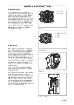
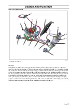
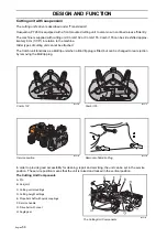
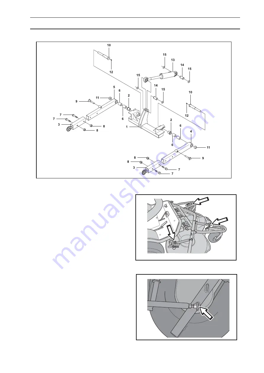
The hydraulic lifting cylinder's (13) piston rod
is connected to a lateral member (1), which
has two forward facing lifting arms (4+5) with
attachment arms (3).
The cutting unit is suspended at the rear
edge in the two attachment arms with link
joints and pins. At the front are two swivel
castors.
An electro-hydraulic function gives a weight
transfer to the machine, to reduce the ground
pressure of the attachment.
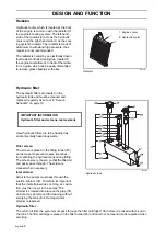
The mowing height setting is made using
three knobs, two at the front and one at the
back.
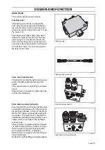
The tilt angle is adjusted using an adjuster
screw on the right-hand side of the cover.
8043-139
Lift system
8043-047
Mowing height settings
8009-787
Adjustment screw tilt angle
Summary of Contents for PT 26D
Page 1: ...Workshop manual PT26D English ...
Page 13: ...English 12 SPECIAL TOOLS ...
Page 94: ...English 93 REPAIR INSTRUCTIONS 8043 197 Cutting unit Combi 155 ...
Page 107: ...English 106 REPAIR INSTRUCTIONS ...
Page 123: ...English 122 REPAIR INSTRUCTIONS ...
Page 145: ......
Page 146: ...English 145 APPENDIXES Circuit diagram Circuit diagram 1 ...
Page 147: ...English 146 APPENDIXES Circuit diagram 2 ...
Page 148: ...English 147 APPENDIXES Circuit diagram 3 ...
Page 149: ...English 148 APPENDIXES Circuit diagram 4 ...
Page 150: ...English 149 APPENDIXES Circuit diagram 5 ...
Page 151: ...English 150 APPENDIXES Circuit diagram 6 ...
Page 152: ...English 151 APPENDIXES Circuit diagram 7 ...
Page 153: ...English 152 APPENDIXES Circuit diagram 8 ...
Page 154: ...English 153 APPENDIXES Circuit diagram 9 ...
Page 155: ...English 154 APPENDIXES Circuit diagram 10 ...
Page 156: ...English 155 APPENDIXES Circuit diagram 11 ...
Page 157: ...English 156 APPENDIXES ...
Page 161: ...English 160 APPENDIXES 8043 160 Circuit board placement ...
Page 162: ...English 161 APPENDIXES Hydraulic diagram 8043 247 Hydraulic diagram ...
Page 163: ...English 162 APPENDIXES ...
Page 167: ...2009W18 115 08 30 26 ...

