English-
70
REPAIR INSTRUCTIONS
Fuel and intake system
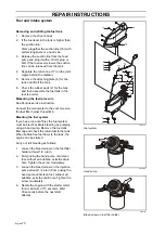
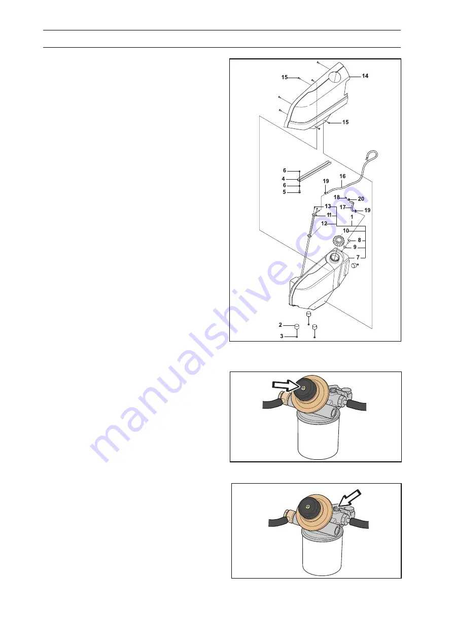
Removing and refitting thefuel tank
1.
Remove the driver’s seat.
2.
If the fuel level in the tank is higher than
the suction line:
Clamp together the suction line (16) with
self-locking pliers or a hand vice.
3.
Release the suction line from the feed
pump and plug it with a 10 mm plug or
bolt. If the fuel level is lower, the suction
line can be released from the tank.
4.
Separate the return line (17) on the joint
nipple behind the radiator.
5.
Remove the attaching plate (4) for the
tank and lift off the tank.
6.
Check the rubber pads (2) for the tank
and then assemble the fuel tank in the
reverse order.
Measuring the feed pressure
See Perkins service instruction.
Connect the manometer to the vent screw on
the fuel filter holder, thread M6.
Bleeding the fuel system
If you have run out of fuel, the fuel system
must be bled. Facilitate bleeding by pumping
using a hand pump. Remove the fuel tank
filler cap and check the return fuel to the tank.
When bubble free fuel flows to the tank, the
engine can be started.
Carry out full bleeding as follows:
1.
Loosen the bleed screw on the fuel filter
holder at least 1/2 a turn.
2.
Pump using the hand pump until clean
fuel, without air bubbles, exits the drain
hole. Tighten the screw moderately.
3.
Loosen the bleed screw on the injection
pump at least 1/2 a turn. Pump using the
hand pump until clean fuel, without air
bubbles, exits the drain hole. Tighten the
screw moderately.
4.
Rotate the engine with the starter motor
for a maximum of 15 seconds. Wait
30 seconds before the next start
attempt.
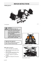
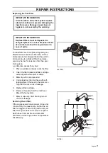
8043-192
Fuel system
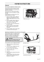
8009-774
Hand pump
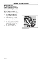
8009-782
Bleed screw on fuel filter holder
Summary of Contents for PT 26D
Page 1: ...Workshop manual PT26D English ...
Page 13: ...English 12 SPECIAL TOOLS ...
Page 94: ...English 93 REPAIR INSTRUCTIONS 8043 197 Cutting unit Combi 155 ...
Page 107: ...English 106 REPAIR INSTRUCTIONS ...
Page 123: ...English 122 REPAIR INSTRUCTIONS ...
Page 145: ......
Page 146: ...English 145 APPENDIXES Circuit diagram Circuit diagram 1 ...
Page 147: ...English 146 APPENDIXES Circuit diagram 2 ...
Page 148: ...English 147 APPENDIXES Circuit diagram 3 ...
Page 149: ...English 148 APPENDIXES Circuit diagram 4 ...
Page 150: ...English 149 APPENDIXES Circuit diagram 5 ...
Page 151: ...English 150 APPENDIXES Circuit diagram 6 ...
Page 152: ...English 151 APPENDIXES Circuit diagram 7 ...
Page 153: ...English 152 APPENDIXES Circuit diagram 8 ...
Page 154: ...English 153 APPENDIXES Circuit diagram 9 ...
Page 155: ...English 154 APPENDIXES Circuit diagram 10 ...
Page 156: ...English 155 APPENDIXES Circuit diagram 11 ...
Page 157: ...English 156 APPENDIXES ...
Page 161: ...English 160 APPENDIXES 8043 160 Circuit board placement ...
Page 162: ...English 161 APPENDIXES Hydraulic diagram 8043 247 Hydraulic diagram ...
Page 163: ...English 162 APPENDIXES ...
Page 167: ...2009W18 115 08 30 26 ...

