English-
73
REPAIR INSTRUCTIONS
Chassis
Checking and adjusting the throttle control
Check that the engine responds to throttle
increases and that a good engine speed is
attained at full throttle.
Front stop screw for max speed is sealed.
Breaking the seal can invalidate the engine
warranty.
If adjustments are necessary, they can be
made as follows for the cable:
1.
Move the throttle control to maximum
speed and check that the arm for the
regulator lightly supports the front stop
screw.
2.
Move the throttle control to idling and
check that the arm for the regulator
supports the rear stop screw.
3.
If necessary, move the cable casing in
its rear mounting.
4.
Start the engine and check the idling
speed. Adjust the rear stop screw if
necessary.
5.
Move the throttle control to max. speed
and check the maximum speed.
Adjusting the hydrostatic control and the neutral position
If the machine tends to run forwards or back-
wards when the engine is running and the
pedals are unaffected, the spring tension at
the pump’s control arm can be altered by
turning the eccentric cam by the spring.
The hydrostatic control is adjusted as follows:
1.
Raise the machine so that the wheels
rotate freely.
2.
Loosen the lock nut slightly, the eccen-
tric cam should be hard to turn.
3.
Turn the eccentric using a spanner.
4.
Tighten the locking nut.
5.
Test drive.
6.
Stop the engine and repeat from point 2
if necessary.
7.
Check the status of the LED, to ensure
that the sensor is activated when the
pedals are unactuated.
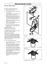
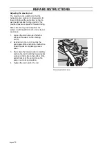
8009-913
Throttle control cable
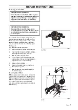
8009-875
Hydrostatic control
WARNING!
Incorrect adjustment may cause
dangerous machine handling.
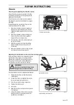
8043-109
Hydrostatic control sensor
Summary of Contents for PT 26D
Page 1: ...Workshop manual PT26D English ...
Page 13: ...English 12 SPECIAL TOOLS ...
Page 94: ...English 93 REPAIR INSTRUCTIONS 8043 197 Cutting unit Combi 155 ...
Page 107: ...English 106 REPAIR INSTRUCTIONS ...
Page 123: ...English 122 REPAIR INSTRUCTIONS ...
Page 145: ......
Page 146: ...English 145 APPENDIXES Circuit diagram Circuit diagram 1 ...
Page 147: ...English 146 APPENDIXES Circuit diagram 2 ...
Page 148: ...English 147 APPENDIXES Circuit diagram 3 ...
Page 149: ...English 148 APPENDIXES Circuit diagram 4 ...
Page 150: ...English 149 APPENDIXES Circuit diagram 5 ...
Page 151: ...English 150 APPENDIXES Circuit diagram 6 ...
Page 152: ...English 151 APPENDIXES Circuit diagram 7 ...
Page 153: ...English 152 APPENDIXES Circuit diagram 8 ...
Page 154: ...English 153 APPENDIXES Circuit diagram 9 ...
Page 155: ...English 154 APPENDIXES Circuit diagram 10 ...
Page 156: ...English 155 APPENDIXES Circuit diagram 11 ...
Page 157: ...English 156 APPENDIXES ...
Page 161: ...English 160 APPENDIXES 8043 160 Circuit board placement ...
Page 162: ...English 161 APPENDIXES Hydraulic diagram 8043 247 Hydraulic diagram ...
Page 163: ...English 162 APPENDIXES ...
Page 167: ...2009W18 115 08 30 26 ...


