English-
84
REPAIR INSTRUCTIONS
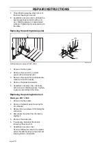
Replacing the power take-off belts
Always replace the belts in pairs.
1.
Remove the driver’s seat.
2.
Remove the protective cover above the
hydraulic pump's drive shaft.
3.
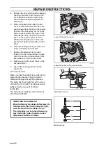
Secure the injection pump stop arm
backward in position for engine stopping.
4.
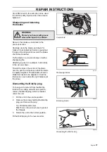
Release the drive shaft from the hydrau-
lic pump and remove the spacer
ring (102) from the coupling.
5.
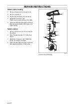
Release the belt tensioner’s spring ten-
sion, two springs.
6.
Pry off the belt from the rear belt pulley
and guide it through the belt tensioner to
the rear of the belt pulley.
7.
Pry off the front belt from the lower belt
pulley and guide it through the belt ten-
sioner to the rear of the belt pulley.
8.
Pry off both belts from the crankshaft
belt pulley and guide it through the gap
between the drive shaft and the hydrau-
lic pump.
9.
Install a new belt in reverse order. Insert
both belts between drive axle and
hydraulic pump.
First lay both belts on the crankshaft belt
pulley and then the front belt on the
lower belt pulley.
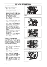
Belt tensioner power take-off belt
The roller (114) can be removed without dis-
mantling the belt tensioner. Release the belt
tensioner’s spring tension and move the belts
to one side, the roller is now accessible from
the right-hand side of the machine.
Dismantling of the belt tensioner:
1.
Release the belt tensioner’s spring ten-
sion, two springs.
2.
Remove the belt tensioner's bearing
bolt (119).
3.
Remove the rear bearing bracket's
screws (109+110).
4.
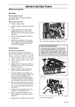
Pry off the belts from the lower belt
pulley (92) and guide them through the
belt tensioner to the rear of the belt
pulley.
5.
Remove the belt tensioner’s roller (114).
6.
Remove the belt tensioner (117). Angle it
anti-clockwise, so it fits between pulley
and the frame.
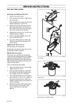
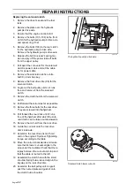
8009-885
Stop arm
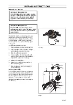
8043-113
Drive axle
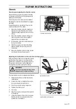
8043-059
Belt tensioner spring attachments
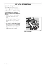
8043-060
Dismantling position at the lower belt pulley
8043-135
Belt tensioner
Summary of Contents for PT 26D
Page 1: ...Workshop manual PT26D English ...
Page 13: ...English 12 SPECIAL TOOLS ...
Page 94: ...English 93 REPAIR INSTRUCTIONS 8043 197 Cutting unit Combi 155 ...
Page 107: ...English 106 REPAIR INSTRUCTIONS ...
Page 123: ...English 122 REPAIR INSTRUCTIONS ...
Page 145: ......
Page 146: ...English 145 APPENDIXES Circuit diagram Circuit diagram 1 ...
Page 147: ...English 146 APPENDIXES Circuit diagram 2 ...
Page 148: ...English 147 APPENDIXES Circuit diagram 3 ...
Page 149: ...English 148 APPENDIXES Circuit diagram 4 ...
Page 150: ...English 149 APPENDIXES Circuit diagram 5 ...
Page 151: ...English 150 APPENDIXES Circuit diagram 6 ...
Page 152: ...English 151 APPENDIXES Circuit diagram 7 ...
Page 153: ...English 152 APPENDIXES Circuit diagram 8 ...
Page 154: ...English 153 APPENDIXES Circuit diagram 9 ...
Page 155: ...English 154 APPENDIXES Circuit diagram 10 ...
Page 156: ...English 155 APPENDIXES Circuit diagram 11 ...
Page 157: ...English 156 APPENDIXES ...
Page 161: ...English 160 APPENDIXES 8043 160 Circuit board placement ...
Page 162: ...English 161 APPENDIXES Hydraulic diagram 8043 247 Hydraulic diagram ...
Page 163: ...English 162 APPENDIXES ...
Page 167: ...2009W18 115 08 30 26 ...

