English-
85
REPAIR INSTRUCTIONS
7.
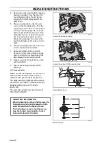
Lubricate the belt tensioner’s axle bush-
ing with corrosion inhibiting grease or
copper-based lubricant and thread it in
the belt tensioner.
8.
Assemble in reverse order. Tightening
torque for screws as set out in the table.
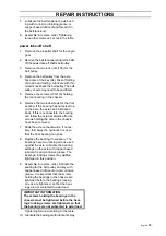
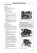
power take-off shaft
1.
Remove the propeller shaft for the angle
gear.
2.
Remove the belt tensioner and pry the belts
off the power take-off shaft’s belt pulley.
3.
Remove the two lock nuts (105) for the
belt pulley.
4.
Remove the belt pulley from the axle.
Take care of the key (94). Risk of fretting
corrosion and cutting. Lubricate with thin
oil and knock back the belt pulley. The belt
pulley or axle may need to be sacrificed.
5.
Remove the screws (109+110) holding
the rear bearing in the chassis.
6.
Remove the two lock screws for the front
bearing. If the bearing has not seized up
on the axle, the axle can be knocked
back. If this is not possible, the bearing
can follow the axle backwards after the
screws holding the axle in the chassis
have been removed.
7.
Slide the axle out backwards. If neces-
sary, fold away the hydraulic hoses so
that the front bearing can pass.
8.
Replace the bearing if necessary. The
bearings have two locking screws each
against the axle. Lubricate the bearing
settings on the axle with copper-based
lubricant or anti-corrosive grease. The
bearings’ locking screws may
not be
tightened in this position.
9.
Assemble in reverse order, lubricate the
seating for the belt pulley and key with
copper-based lubricant or anti-corrosive
grease. It is important that the screws
holding the bearings in the chassis are
tightened before the bearings’ locking
screws are tightened, so that the bear-
ings are not subjected to axial load.
Tightening torque according to the table.
10. Lubricate the bearings with lubricant spray.
IMPORTANT INFORMATION
The screws holding the bearings in the
chassis must be tightened before the bear-
ings’ locking screws are tightened, so that
the bearings are not subjected to axial load.
Summary of Contents for PT 26D
Page 1: ...Workshop manual PT26D English ...
Page 13: ...English 12 SPECIAL TOOLS ...
Page 94: ...English 93 REPAIR INSTRUCTIONS 8043 197 Cutting unit Combi 155 ...
Page 107: ...English 106 REPAIR INSTRUCTIONS ...
Page 123: ...English 122 REPAIR INSTRUCTIONS ...
Page 145: ......
Page 146: ...English 145 APPENDIXES Circuit diagram Circuit diagram 1 ...
Page 147: ...English 146 APPENDIXES Circuit diagram 2 ...
Page 148: ...English 147 APPENDIXES Circuit diagram 3 ...
Page 149: ...English 148 APPENDIXES Circuit diagram 4 ...
Page 150: ...English 149 APPENDIXES Circuit diagram 5 ...
Page 151: ...English 150 APPENDIXES Circuit diagram 6 ...
Page 152: ...English 151 APPENDIXES Circuit diagram 7 ...
Page 153: ...English 152 APPENDIXES Circuit diagram 8 ...
Page 154: ...English 153 APPENDIXES Circuit diagram 9 ...
Page 155: ...English 154 APPENDIXES Circuit diagram 10 ...
Page 156: ...English 155 APPENDIXES Circuit diagram 11 ...
Page 157: ...English 156 APPENDIXES ...
Page 161: ...English 160 APPENDIXES 8043 160 Circuit board placement ...
Page 162: ...English 161 APPENDIXES Hydraulic diagram 8043 247 Hydraulic diagram ...
Page 163: ...English 162 APPENDIXES ...
Page 167: ...2009W18 115 08 30 26 ...

