English-
91
REPAIR INSTRUCTIONS
Adjustments cutting unit
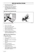
Setting the cutting height and tilt angle
When a new cutting unit is attached, you
need to adjust the tilt angle and cutting
height.
Adjustment must be made in the stated
order.
Starting position:
•
Check the tyre pressures 100 kPa /
1.0 bar / 14.5 PSI and 150 kPa / 1.5 bar /
21.7 PSI for the pivot wheels.
•
The cutting unit must be lowered on a
flat surface.
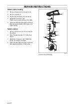
Cutting height
1.
Release the cutting height setting handle.
2.
Set the same height at all three setting
points.
3.
Tighten the cutting height handle by hand.
4.
Set the handle for cutting height setting.
Release the handle by pressing in the
button and turning it to the horizontal
position, so that it does not catch on
bushes etc.
The height interval is between 25-127 mm
(1"- 5"), 7 positions.
Tilt angle
The machine must be on a flat surface.
1.
Check the tyre pressures 100 kPa /
1.0bar / 14.5 PSI and 150 kPa / 1.5 bar /
21.7 PSI for the pivot wheels.
2.
Measure the distance between the
ground and the front and rear edges of
the unit.
3.
The cutting unit’s rear edge must be
6-9 mm (1/4"-3/8") higher than the unit’s
front edge.
4.
Unscrew the lock nut and turn the adjust-
ment screw. Extend the stay in order to
raise the rear edge of the cutting unit.
5.
Then tighten the lock nut to the mounting.
IMPORTANT INFORMATION
When replacing the cutting unit, you must
readjust the tilt angle and cutting height.
8043-053
Cutting height setting, rear
8043-046
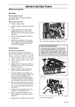
Cutting height setting, front
8009-787
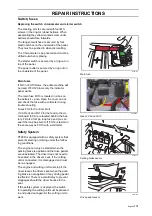
Adjusting the tilt angle
Summary of Contents for PT 26D
Page 1: ...Workshop manual PT26D English ...
Page 13: ...English 12 SPECIAL TOOLS ...
Page 94: ...English 93 REPAIR INSTRUCTIONS 8043 197 Cutting unit Combi 155 ...
Page 107: ...English 106 REPAIR INSTRUCTIONS ...
Page 123: ...English 122 REPAIR INSTRUCTIONS ...
Page 145: ......
Page 146: ...English 145 APPENDIXES Circuit diagram Circuit diagram 1 ...
Page 147: ...English 146 APPENDIXES Circuit diagram 2 ...
Page 148: ...English 147 APPENDIXES Circuit diagram 3 ...
Page 149: ...English 148 APPENDIXES Circuit diagram 4 ...
Page 150: ...English 149 APPENDIXES Circuit diagram 5 ...
Page 151: ...English 150 APPENDIXES Circuit diagram 6 ...
Page 152: ...English 151 APPENDIXES Circuit diagram 7 ...
Page 153: ...English 152 APPENDIXES Circuit diagram 8 ...
Page 154: ...English 153 APPENDIXES Circuit diagram 9 ...
Page 155: ...English 154 APPENDIXES Circuit diagram 10 ...
Page 156: ...English 155 APPENDIXES Circuit diagram 11 ...
Page 157: ...English 156 APPENDIXES ...
Page 161: ...English 160 APPENDIXES 8043 160 Circuit board placement ...
Page 162: ...English 161 APPENDIXES Hydraulic diagram 8043 247 Hydraulic diagram ...
Page 163: ...English 162 APPENDIXES ...
Page 167: ...2009W18 115 08 30 26 ...


