background image

7  

B R A K E S 

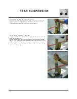
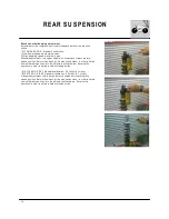
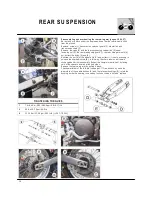
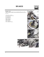
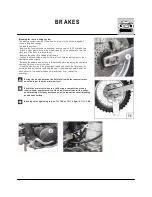
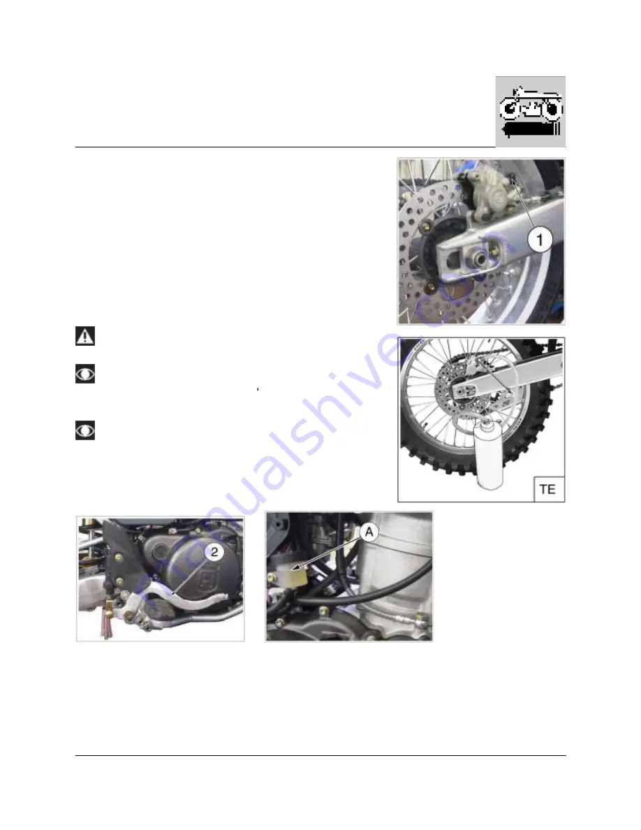
B le e d in g  th e  re a r  b re a k in g  s ys te m 
T h e  b ra kin g  s yste m  m u st  b e  b le d  w h e n ,  d u e  to  a ir  in  th e  circu it,  th e  p e d a l 
stro ke  is  lo n g  a n d  sp o n g y. 
T o  b le e d  th e  s yste m : 
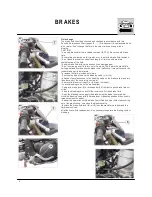
-  R e m o ve  th e  re s e rvo ir  co ve r  ru b b e r  b o o t  a n d  to p  u p  w ith  (D O T  4 )  b ra ke  flu id . 
-  A tta ch  a  cle a r  p la stic  h o se  to  th e  b le e d  va lve  (1 )  o n  th e  ca lip e r  a n d  tu rn  th e 
o th e r  e n d  o f  th e  h o se  in to  a  co n ta in e r. 
-  D e p re ss  th e  p e d a l (2 )  a n d  ke e p  it  fu ll d o w n . 
-  L o o se n  th e  b le e d  u n io n  le ttin g  o u t  flu id  (a t  first,  o n ly  a ir  w ill co m e  o u t),  th e n , 
clo sin g  th e  u n io n  slig h tly. 
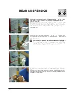
-  R e le a se  th e  p e d a l a n d  w a it  fo r  a  fe w  se co n d s  b e fo re  re p e a tin g  th e  o p e ra tio n 
u n til o n ly  flu id  co m e  o u t  o f  th e  tu b e . 
-  C lo se  th e  b le e d  u n io n  to  th e  p re scrib e d  to rq u e  a n d  ch e ck  th e  flu id  le ve l (A ) 
in sid e  th e  re se rvo ir  b e fo re  re p la cin g  th e  ca p .  If  th e  b le e d in g  o p e ra tio n  h a s  b e 
d o n e  co rre ctly,  th e  p e d a l  w ill h a ve  n o  m u sh y  fe e l.  If  n o t,  re p e a t  th e 
o p e ra tio n . 

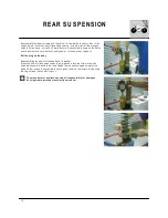
D u rin g  th e  b le e d  o p e ra tio n  th e  flu id  le ve l  in s id e  th e  re s e rvo ir  m u s t 
n e ve r  b e  lo w e r  th a n  th e  m in im u m  le ve l. 

S h o u ld  th e  m o to rc yc le ,  d u e  to  a  fa ll  d u rin g  a  c o m p e titio n  o r  s h o p 
re p a irs ,  s h o w  so m e  e la s tic ity  o f  th e  b ra k e  le ve r  s tro k e , w ith  a  s u b s e -
q u e n t  b ra k in g  e ffic ie n c y  d e c re a s e ,  yo u ll  to  re p e a t  th e  c irc u it  b le e d in g 
a s  a b o ve  d e s c rib e d . 

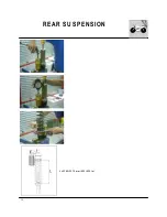
B le e d in g  va lve  tig h te n in g  to rq u e :  1 2 ÷1 6  N m /  1 ,2 ÷1 ,6  K g m /  8 .7 ÷1 1 .6  ftlb 

Summary of Contents for SM 610 2006

Page 1: ...1 W orkshop Manual SM 610 TE 610 2006 Part N 8000 A4640 04 2005 ...

Page 2: ...0 ZCG AFEKP 6V400000 TE 610 ZCGEAEKP 6V300000 To the best knowledge of M V Agusta M otorcycles S p A Varese Inc the m aterial contained herein is accurate as of the date this publication was approved for printing Cagiva M otor S p a Varese Inc reserves the right to change specifications equipm ent or designs at any tim e without notice and without incurring obligation Illustrations in this m anual...

Page 3: ...m proper operation of the m otorcycle and form ulate proper clearing questions about the sym ptom s of the trouble detect clearly the cause of the trouble This m anual gives the theoretical bases which however shall be integrated by the per sonal experience and by the attendance to training courses periodically organized by HUSQVARNA rationally plan the repair work in order to prevent dead tim e a...

Page 4: ...4 W here not otherwise specified data and instructions refer to all m odels SM 610 TE 610 ...

Page 5: ...General operations E Engine disassem bly F Engine overhauling G Engine re assem bly H Front suspension I Rear suspension J Brakes L Electric system M Engine cooling system N Lubrication circuit O Specific tools W Torque w rench settings X Fram e w heels Y Notes for USA CDN AUS m odels Z Sum m ary ...

Page 6: ...6 ...

Page 7: ...1 GENERAL Section ...

Page 8: ... 3 Lubrication A 3 Cooling A 3 Ignition A 3 Starting A 3 Transm ission A 4 Fram e A 5 Suspensions A 5 Brakes A 5 W heels A 5 Tires A 5 Ignition system electric system A 6 W eights A 7 Overall dim ensions A 7 Table of Contents Capacities A 8 GENERAL ...

Page 9: ...old engine INTAKE 0 002 in EXHAUST 0 002 in FUEL FEEDING Gravity Dry type air filter Carburetor type Keihin FCR M X 41 with acceleration pum p and T P S Throttle Position Sensor LUBRICATION Forced type with lobe twin pum p COOLING By fluid with double cooler electric fan and expansion tank IGNITION Electronic with capacitive discharge Digital controlled variable spark advance Spark plug type NGK C...

Page 10: ... z 34 13 2nd gear 1 812 z 29 16 3rd gear 1 350 z 27 20 4th gear 1 091 z 24 22 5th gear 0 916 z 22 24 6th gear 0 769 z 20 26 Final drive Drive between gearbox and rear wheel by 5 8 x 1 4 chain with O Rings Transm ission sprocket z 15 Rear wheel sprocket z 45 Transm ission ratio 3 000 Rear chain size 5 8 x1 4 112 links Total drive ratios 1st gear 18 389 2nd gear 12 744 3rd gear 9 492 4th gear 7 670 ...

Page 11: ...area 5 02 sq in TE 6 14 sq in SM Independent hydraulic circuit and pum p with control on the handlebar right side Rear Drilled floating disc ø 8 66 in with floating caliper Pads area 4 57 sq in Independent hydraulic circuit controlled by pedal and pum p on the m otorcycle right side W HEELS Rim s Front TE TAKASAGO Excel in light alloy 1 6x21 Front SM SANREM O in light alloy 3 50x17 Rear TE M etzel...

Page 12: ...e control switch The electric system includes the follow ing elem ents SM Headlam p with two filam ents bulb of 12V 55 60W and parking light bulb of 12V 5W TE Headlam p with two filam ents bulb of 12V 35 35W and parking light bulb of 12V 3W Rear lights with stop bulbs of 12V 21W and parking light bulb of 12V 5W Turn signals bulb of 12V 10W Three15 A fuses one of them is a spare fuse Battery 12V 12...

Page 13: ...7 W EIGHTS DIM ENSIONS m m GENERAL SM 610 TE 610 Curb weight without fuel SM 610 kg 142 313 lbs TE 610 kg 140 308 6 lbs ...

Page 14: ...il level Oil for rear shock absorber AGIP FORK 2 5 SAE 2 5 Fluid for cooling system AGIP COOL 2 45 Im p Pints 2 85 U S Pints Front brake fluid AGIP BRAKE 4 DOT 4 Rear brake fluid AGIP BRAKE 4 DOT 4 Drive chain lubrication AGIP CHAIN LUBE Grease lubrication AGIP BIKE GREASE Electric contact protection AGIP ROCOL M OISTURE GUARD Fillers for radiator AREXONS liquido Air filter oil AGIP FORM ULA FILTE...

Page 15: ...1 Section MAINTENANCE ...

Page 16: ...le control Check Adjust play Choke control Check operation Flexible controls and transm issions Check Adjust Drive chain Check Adjust Tires Check pressure Side stand Check operation Electrical equipment Check operation Instrum ent panel Check operation Lights Visual signals Check operation Horn Check operation Headlight Check operation Ignition switch Check operation Locks Check operation Screws a...

Page 17: ...ystem chain S Clutch flexible coupling C Ignition cover C C C Starting gears assem bly C Connecting rod S Clutch discs C Ignition tim ing C Fuel filter C S S S Carburetor C C P Carburetor throttle valve C Air filter P S S S Engine oil pressure C Cylinder Piston checking C C Brakes fluid C C C S C Brakes hydraulic controls C C C C C Brakes pads wear C C Flexible controls C C L L L Throttle control ...

Page 18: ...ithin 24 m onths Only if reached within 24 m onths Rim s spokes stretch C C C C C Steering head bearings play C C C Transm ission chain Chain rollers C C L C L S C L S Rear sprocket Pinion C S C S Side stand screws C C C C C C W heels hubs bearings C C Fuel tank P P Front fork oil S R S R Bolts and nuts general tightening C C C C C C Lubricating Greasing C L L L L L Locks C M otorcycle general tes...

Page 19: ...1 TROUBLESHOOTING Section ...

Page 20: ...park plug dirty or wet Clean or dry 3 Spark plug gap too large Adjust 4 Ignition coil faulty Replace 5 H T leads dam aged or short circuiting Check 6 Electronic device faulty Replace 7 R H switch faulty Replace Fuel not reaching carburetor 1 Fuel tank cap breather blocked Clean 2 Fuel cock blocked Clean 3 Fuel feed hose blocked Clean 4 Carburetor fuel filter dirty Clean 5 W orn out float valve or ...

Page 21: ...t 6 Valve springs weak or seized Replace 7 Cam chain worn Replace Crankshaft noise 1 M ain bearings worn Replace 2 High radial and axial play at con rod big end Replace 3 Crankshaft gear dam aged Replace 4 Crankshaft nut loose Tighten Clutch noise 1 Discs worn Replace 2 Excessive free play between clutch drum and driving discs Replace Gearbox noise 1 Gears worn Replace 2 Gear splines worn Replace ...

Page 22: ...nes gearshift forks control shaft worn Replace 5 Gearshift forks control pins worn Replace Engine lacks pow er 1 Air filter dirty Clean 2 Carburetor m ain jet blocked or wrong size Clean or replace 3 Poor quality fuel Replace 4 Intake m anifold loose Tighten 5 Spark plug gap too large Adjust 6 Inadequate com pression Find cause 7 Incorrect valve play Adjust 8 Faulty valve guides or seats Replace 9...

Page 23: ...n Replace Suspension too hard 1 Insufficient oil in front fork stanchions Top up 2 Too low viscosity of front fork stanchion oil Replace 3 W eak front fork spring Replace 4 W eak rear shock absorber spring Replace 5 Rear shock absorber badly adjusted Adjust W heel front and rear vibrates 1 W heel rim bent Replace 2 W heel hub bearings worn Replace 3 W heel spokes loose Tighten 4 W heel axle nut lo...

Page 24: ...ean Adjust carburetor 2 Spark plug gap too sm all Adjust 3 Too high heat rating Replace the spark plug Generator charging too low or not at all 1 W ires to voltage regulator connected incorrectly or short circuiting Connect correctly or replace 2 Faulty voltage regulator Replace 3 Generator coil faulty Replace Generator charging too high 1 Voltage regulator faulty Replace The battery is discharged...

Page 25: ...1 SETTINGS AND ADJUSTMENTS Section ...

Page 26: ...ing the bag filters D 6 Coolant level check D 6 Replacem ent of coolant D 7 Air filter check and cleaning D 8 Throttle cable adjustm ent D 9 Clutch adjustm ent D 10 Adjustm ent of front brake control lever and fluid level D 11 Adjustm ent of rear control pedal D 12 Steering bearings play adjustm ent D 13 Front fork adjustm ent and oil level checking D 14 Adjusting the shock absorber D 15 Secondary...

Page 27: ...w caps and checks the valve play using a gauge The play m ust be 0 002 in both for the intake and the exhaust lf the above play is not m et loosen the counter nuts 1 and act as required other screws 2 until the required play is obtained Torque again the counter nuts 1 and install all parts previously rem oved Spark plug 8 8 ft lb L H cover fastening screw 5 8 ft lb Nut for valve adjusting screw 5 ...

Page 28: ...crew 1 to obtain the slow running required Idle adjustm ent Adjust the carburetor with warm engine and with the throttle control in closed position Proceed as follows Turn slow running adjusting screw 1 on the left side of the bike near the fuel cock until the required idle condition is reached turn the screw clockwise to increase the engine r p m and counterclockwise to decrease the engine r p m ...

Page 29: ...45 Kgm 18 1 ft lb M 22 plug 60 Nm 6 1 Kgm 44 ft lb Add the required am ount of oil through the oil filler see page A 8 Slowly turn the engine for som e m inutes the turn it off and wait for som e m inutes to allow the oil setting inside the sum p W ith the m otorcycle set in vertical position and looking through window C check that the level is between the two notches A and B placed at the back of...

Page 30: ...lant level check Check the level 2 in the right radiator with cold engine and with m otorcycle in vertical position The cooler m ust be flush with the lower side of the filling pipe union The level inside the expansion tank m ust never be under the M IN 1 Otherwise ALW AYS and ONLY fill through the plug under the right radiator or from the expansion cap in case of level restoration Avoid rem oving...

Page 31: ...in screw A set on the right of the cylinder W hen the fluid is fully drained reassem ble the drain screw check the gasket tightening torque 9 3 Nm 0 95 Kgm 6 9 ft lb and fill the right reservoir with the required quantity see page A 8 Slowly run the engine to elim inate possible air bubbles then check the levels again following the instructions on page D 6 ...

Page 32: ...lean foam air detergent fluid or sim ilar then dry it fully Plunge the filter in special oil for filters AGIP Foam air filter protection oil or sim ilar then wring it to drain superfluous oil Do not use gasoline or a low flash point solvent to clean the elem ent A fire or explosion could result Clean the elem ent in a well ventilated area and do not allow sparks or flam es anywhere near the workin...

Page 33: ...rewing it the clearance is reduced while by screwing screw 4 it is increased tighten the counter ring nut again 3 Operation w ith dam aged throttle cable could result in an unsafe riding condition In case of throttle control cables 1 and 2 replacem ent it is necessary to respect during reassem bly the m easure A 10m m 0 4 in as shown in the picture Then reassem ble guard cover B using screw 3 and ...

Page 34: ...ed 6 Set the clutch Iever keeping a distance L 4 35 4 43 in on the crankcase FIGURE 1 Install the friction disk 7 Put first a Iined disk then alternatively a non lined disk with a Iined disk Total quantity is eight Iined disks with seven non Iined disks Install the bearing 8 the washer 9 disk thrust plate 10 with six springs and rela tive bolts 11 Tighten to a torque value of 7 3 ft Ib Align the i...

Page 35: ...which braking starts Turn the adjuster a CLOCKW ISE in order to position the m aster cylinder in such a way that braking occurs im m ediately upon lever action Turn the adjuster a COUNTERCLOCKW ISE in order to position the m aster cylinder in such a way that braking occurs slightly afterwards upon lever action The front fluid m ust not be lower than the m inim um level 1 see from the pum p inspect...

Page 36: ...wise loosen lock nut 3 and work on control rod 4 until the right play is reached tighten lock nut 3 Never lower the play under 0 08 in on the brake pum p The fluid level m ust be between M IN and M AX of pum p tank If the brake lever feels m ushy w hen it is applied there m ay be air in the brake lines or the brake m ay be defective CHECK THE BRAKING SYSTEM page L 7 If the lever free play is exces...

Page 37: ...ebars should also rotate without effort Stand in front of the m otorcycle and grasp the lower end of the fork legs m oving them in the perpendicular direction to their axis If play is noticed proceed with adjustm ent as follows loosen steering sleeve nut 1 loosen four screws that fix steering head to fork legs 3 turn the steering ring nut 2 clockwise of the steering sleeve using a proper tool to a...

Page 38: ...tion turn the register anticlockwise Reverse the operation in order to obtain a harder action c AIR VENT to carry out after each com petition or m onthly Set the m otorcycle on a central stand and release the fork fully and loosen the air vent valve D Once this operation is over tighten the valve Never force the adjusting screw s beyond the m axim um opening and closure positions Oil fork level Fo...

Page 39: ... as shown on page E 14 2 Clean ringnut 1 and adjusting nut 2 of the spring 3 Either with a hook wrench or an alum inum punch loosen the ringnut 4 Turn the adjusting nut as required 5 W hen the adjusting operation is over tighten the ringnut Torque for both ringnuts 5 Kgm 49 Nm 36 2 ft lb Shock absorber hydraulic brake adjustm ent A COM PRESSION Standard adjustm ent 1 Low dam ping speed m axim um o...

Page 40: ...wheel axle loosen the nuts 2 on both sides of the chain adjusters then operate the adjusting screws 3 till the correct tension is restored m ake sure that both the chain streighteners are aligned on the sam e notch tighten the nuts 2 22 5 Nm 2 3 Kgm 16 6 lb ft tighten nut 1 of the wheel axle 142 Nm 14 5 Kgm 104 8 lb ft check again the chain tension After the adjustm ent always check the wheel alig...

Page 41: ...1 GENERAL OPERATIONS Section ...

Page 42: ...and carburetor E 5 Rem oval of conveyors and fuel tank E 6 Rem oval of exhaust system E 7 Rem oval of electrical connections and spark plug cap E 8 Rem oval of cooling system hoses E 8 Rem oval of cooling fan radiators and coolant expansion tank E 10 Rem oval of engine from the fram e E 11 Rem oval of rear fram e w ith fender E 12 ...

Page 43: ...ATIONS Forew ord The operations described in this section are referred to the rem oval of the engine from the m otorcycle further operations not di rectly connected to this scope are located at the end of the chapter ...

Page 44: ...of side panels R H side panel Rem ove the R H side panel rear fastening screw 1 Unhook the side panel from the front side of the air filter box L H side panel Rem ove the L H side panel rear fastening screw Unhook the front side of the panel from the conveyor W hen reassem bling rem em ber to fit bushes under the screws ...

Page 45: ...on the cylinder head rem ove the four screw 3 that fasten the air filter box cover the air filter 4 the screw 5 and the air filter box 6 rem ove the breather hose from the air filter box push lightly using a little screwdriver on the T P S connector 7 located on the carburetor in order to detach it from the m ain wiring harness rem ove the carburetor ...

Page 46: ...uel cock 2 on OFF position rem ove the spoilers fastening screws 3 rem ove the fuel tank front fastening screw 4 rem ove the radiator guards front fastening screws 5 detach the two hoses 6 from the R H fuel cock and detach the fuel feeler gauge connector from the m ain wiring harness rem ove the fuel tank ...

Page 47: ...haust pipe NOTE reassem ble the screws 1 and 2 with LOCTITE 243 Loosen the clam p 5 that fastens the central exhaust pipe to the exhaust silencer Rem ove the two silencer fastening screws 6 Rem ove the silencer Rem ove the springs 7 that fasten the front pipes to the central pipe Rem ove the screws 8 the front pipes 9 and 10 then the central pipe 11 ...

Page 48: ...le ground cable battery engine generator cables neutral switch cable and the spark plug cap Rem oval of cooling system hoses Rem ove the radiator cap loosen the lower clam p 1 rem ove the hose then drain the coolant Loosen the clam ps on the others hoses and detach the hoses from the engine Rem ove on the L H side the breather hose between teh cylinder head and the fram e ...

Page 49: ...9 GENERAL OPERATIONS On the L H of the engine rem ove the breather hose 1 the clutch cable 2 the pinion guard 3 the m aster link and the rear chain 4 ...

Page 50: ...the m ain wiring harness rem ove the fan from its holding plate Detach the therm oswitch 6 from the m ain wiring harness Rem ove the grid 2 detach the breather hose 3 rem ove the two screws 4 and the R H radiator Repeat the sam e operations to rem ove the L H radiator then also rem ove the coolant expansion tank 6 ...

Page 51: ...e the upper engine fastening screw 1 then the plate 2 from the engine Rem ove the rear brake pum p guard 3 Rem ove the engine fastening screws 4 and 5 then the swing arm pivot 6 rem ove the respective nuts on the L H SIDE Lift the engine and extract it sideways ...

Page 52: ...sitive cable 3 when reassem bling first connect the RED positive cable 3 then the BLACK negative cable 2 Cut the solenoid starter plastic clam ps 4 rem ove the solenoid starter and the flasher 5 On the R H side detach the voltage regulator 6 connector from the m ain wiring harness W ithout detaching the connection from the m ain wiring harness rem ove the electronic power unit 7 com plete with ela...

Page 53: ...1 ENGINE DISASSEMBLY Section ...

Page 54: ... F 9 Disassem bly of valves F 10 Disassem bly of cylinder F 10 Disassem bly of piston F 11 Disassem bly clutch cover F 12 Rem oval of the starter m otor and holding flange F 13 Disassem bly of clutch F 14 Disassem bly if the gearbox control shaft F 15 Disassem bly of crankcase crankshaft and lay shaft F 16 Disassem bly of the gearbox F 19 Disassem bly of the oil pum p F 20 Disassem bly of the stat...

Page 55: ...3 Flyw heel puller 3 8000 90662 Engine holder 5 8000 39524 Clutch hub retaining w rench 7 8000 39522 Flyw heel disassem bling w rench 10 8000 83254 Crankshaft guard 12 8000 39521 Valves assem bly and reassem bly tool 13 8000 90875 T D C control tool SPECIFIC TOOLS ...

Page 56: ...in the chapter Settings and Adjustm ents page D 5 Rem ove the spark plug and the gear control lever Disassem bly of gear lever M ake a m ark on the shaft showing the position of the gear lever 1 to m ake the reassem bly easier Loosen the screw 2 10 m m wrench and lift away the gear lever ...

Page 57: ...isassem bly of alternator side cover Rem ove the cover 1 with the stator 8 m m wrench and with the gasket Extract the gear with clutch 2 Rem ove the two bushings from alternator cover and from starting m otor hold ing flange ...

Page 58: ...he outer body of the tool blocked with a hexagonal wrench turn the handle clockwise to rem ove the flywheel from the shaft W ithdraw the flywheel com plete of free wheel 5 and the m iddling gear 6 then rem ove the key from the crankshaft cone Rem ove the roller cage 7 and the thrust washer 8 rem ove the screws 9 5m m wrench and check the conditions of the freewheel the working races of the rollers...

Page 59: ...shes 6 Rem ove the pum p housing along with the packing 3 Replace packing every tim e the pum p is disassem bled Rem ove the nut 4 8 m m wrench from the pum p im peller 5 Lift away the im peller Rem ove the spacer 7 with O rings 8 from the water pum p delivery hole If necessary use an iron wire piece with a bent end to rem ove the spacer ...

Page 60: ...nder head cover 3 8 m m wrench Rem ove the tensioner 4 rem ove the central screw 10 m m wrench pay attention to the spring during the nut rem oval the spring the two side screws 8 m m wrench and the tensioner Take the piston to T D C at the end of the com pression phase with the tool cod 800090875 as described at chapter Adjustm ents page D 5 The cylinder head cover is leaded by centering bush Don...

Page 61: ...ok iron wire to recover the cam chain Rem ove the cam shaft 2 with the decom pressor Rem ove the two nuts 1 from the cylinder 13 m m wrench and the two screws 2 on L H side 5m m wrench Rem ove the four head nuts 3 11m m wrench Lift off the cylinder head Rem ove the gasket 4 and use a new gasket at reassem bly Attention at the centering bushes betw een cylinder head and cylinder ...

Page 62: ...t the valve spring com pressor always is straight Otherwise the valve stem can be bent To prevent loss of tension don t com press the valve springs m ore than necessary M ark all parts so that they can be reassem bled correctly If the valve cotters have m ade a burr on the valve stem rem ove it before rem oving the valve Disassem bly of cylinder Lift off the cylinder Tap carefully the existing bos...

Page 63: ...f piston Hold the piston and cover the crankcase with a clean rag The piston 1 is m arked with an arrow on the exhaust side in order to correctly reassem ble it Rem ove a piston pin keeper and press out the piston pin 2 Rem ove the piston ...

Page 64: ...ding the clutch cover 1 Rem ove the clutch cover in order to rem ove the cover use a screwdriver Rem ove the oil screens 2 3 and clean the filter 3 in accordance with the instruction at chapter Settings and Adjustm ents page D 6 Pay attention to the filter 3 reassem bling sense ...

Page 65: ...arting m otor and holding flange Rem ove the two fastening screws 8 m m wrench and the starting m otor 1 Rem ove retaining ring 2 washer 3 flange 4 and related gasket carefully using a m allet on the existing bosses and the second idle gear 5 ...

Page 66: ...clutch springs Rem ove washers springs spring pressure plate 2 washer axial bearing and disc pack A From prim ary shaft gearbox recover rod 3 ball 4 and pressure plate 5 Straighter the safety washer 6 on the nut of the discs hub Hold the clutch hub steady with the tool B Code 800039524 and rem ove the nut 7 with a 27 m m wrench Rem ove the clutch hub 8 the grooved spacer 9 the clutch bell 10 ...

Page 67: ...and the connected shaft 1 Rem ove the two 4 m m Allen screws 2 and rem ove the plate 3 sprocket of the gear sector 4 Using a 13 m m pipe wrench rem ove the screw 5 that secures the gear speed 6 setting pawl including the spring 7 and the plate Rem ove the screw 8 with a 12 m m wrench ...

Page 68: ...curing the crankshaft and lay shaft rem ove the layshaft fastening nut on L H side too Rem ove the lay shaft counterweight 3 and the key Rem ove the two gears A on the crankshaft and the key Rem ove the two screws locking the blade valve 4 and rem ove it Using a 8 m m wrench unlock the 2 screws then rem ove the neutral sensor 5 with seal ring pin and spring W ithdraw the tim ing chain 6 ...

Page 69: ...the L H crankcase If not previously rem oved rem ove the R H oil screen 8 and the L H oil screen 9 for this one rem ove the cover 8 m m wrench Rem ove the oil vapor recovery duct 10 using a 19 m m wrench Rem ove the clutch control rod 11 Pay attention to the filter 8 reassem bling sense ...

Page 70: ...rankcase Install the special tool A n 800089743 and open the crankcases levering on the crankshaft Separate the crankcases with the gearbox assem bly on the left one Place the left half case on the support B cod 800090662 W ithdraw the crankshaft 12 and the lay shaft 13 ...

Page 71: ...arbox Using pliers rem ove the rods 1 on which the forks are hinged Rem ove the forks Rem ove the gear box control group if not previously done Pay attention to the m ating profiles of the gear box control Rem ove the gear box control as a group ...

Page 72: ... oil pum p fasten ing screws 1 8 m m wrench that secure the cover then rem ove all the parts up to the oil pum p drive shaft 2 Disassem bly of the stator From the ignition cover rem oved before rem ove the five Allen screws three 6 m m 1 and two 4 m m 2 then rem ove the stator and the pick up from the L H cover ...

Page 73: ...late 1 between the two flywheel halves Using a press rem ove the connecting rod pin from one of the flywheel halves Rem ove the connecting rod and needle bearing Turn the flywheel over half and press out the crankpin 2 Rem ove the threaded plug and clean connecting rod pin ...

Page 74: ...22 ...

Page 75: ...1 ENGINE OVERHAULING Section ...

Page 76: ...ing G 9 Cam roller replacem ent G 10 Cam shaft G 10 Tim ing chain and gears G 11 Tim ing chain stretcher sliding G 11 Cylinder G 12 Piston G 12 Cylinder piston fitting G 12 Piston diam eter G 12 Gudgeon pin G 12 Gudgeon pin connecting rod sm all end clearance G 13 Piston rings G 13 Piston rings cylinder clearance G 14 Piston rings thickness G 14 Piston ring piston rings groove clearance G 14 Conne...

Page 77: ...t run out G 15 Replacing the sm all end bush G 16 Clutch unit G 16 Clutch housing friction disc clearance G 17 Clutch spring G 17 Gear selector fork and gearing G 17 Fork drum fork pins coupling G 18 Oil pum p G 19 Carburetor overhauling G 20 Carburetor setting G 21 ...

Page 78: ...m free from bare flam es or sparks and that the op erator w ears goggles SPECIFIC TOOLS 12 8000 39521 Valves assem bly and reassem bly tool Assem blies For a good and efficient engine operation it is essential that all assem blies are within the tolerances prescribed In fact a close assem bly causes seizures as soon as the m oving m em bers heat up while a wide assem bly causes vibrations which in...

Page 79: ... the valve into its seat and rotate a few tim es so that it leaves an im pression in the paste During this operation hold the valve stem straight with a chuck vice The im pression left in the paste on the valve seat should be continuous without breaks and the width of the im pression W which corresponds to the thickness of the seat should be within the following lim its W 0 062 0 070 in new engine...

Page 80: ...0 0011 in m arked in W HITE or 0 0023 in m arked in RED Evenly heat the head and keep it for 1 hour at a tem perature of 200 C 392 F Install the valve seats and set the valve seats with special tool Allow to cool then m ill the seats and grind the valves Valve guides Carry out a careful visual check of the valve guides The valve guides should be checked for wear by m easuring the clearance between...

Page 81: ...ure of 200 C 392 F Lubricate the seat with engine oil then insert the guide valve Keep at am bi ent tem perature 20 C 68 F using a suitable drift lubricating with M OLIKOTE G Ream the internal hole A and lubricate Fit the lower valve spring collects lubricate and fit the new seal rings B distinguishing color area C intake and exhaust 47 m m 1 85 in Valve Check that the valve stem and contact surfa...

Page 82: ...gonality check The m ax obliquity is 0 06 in for side Installation of valves Lubricate the valve guides and valve stem with engine oil when the valve is installed Install the seal ring the springs and the cup Use tool code no 800039521 to com press the valve springs and can install halves cones Do not com press the valve springs m ore than necessary Do not dam age the cylinder head Tap gently on t...

Page 83: ...hings Check that the pivot is not worn in this case replace it Use a 6 m m screw to push out the shafts 1 of the rocker arm s 2 Rem ove the rocker arm s Check the rocker arm s for cracks Also check the cam rollers 3 They m ust be intact and without play see page G 25 Check valve adjusters wear Replacem ent of rocker arm bushing If the rocker arm bushings need replacem ent rem ove them with a drift...

Page 84: ...rm and m ount the roller shaft Use a vise Be careful so that the rocker arm isn t dam aged Lock the cam roller shaft with a center punch from each side Cam shaft Check that cam surfaces are scored stepped grooved etc Excessively worn cam s are often the cause of bad engine tim ing thus reducing engine power Insert the cam shaft between two references and then check deviation using two com parators...

Page 85: ...t 10 clicks of its stroke A Check the wear of the driven gear and even if just one of the elem ents is worn out replace all the driven gear and the chain as well Check also the driving gear wear on the crankshaft L H side Tim ing chain stretcher sliding The cam chain tensioners should be replaced when the wear m aterial is worn through ...

Page 86: ...ar lim its are greater than those prescribed then replace the cylinder liner with the piston re boring is not possible since the cylinder liner has been given a special hardening treatm ent Piston diam eter M easure the piston diam eter Dp at a distance B 14 m m 0 55 in from the base The connection play will be Dc Dp Gudgeon pin The gudgeon pin should be perfectly sm ooth without scoring grooving ...

Page 87: ... be 0 00047 0 00106 in M ax adm issible wear lim it 0 0022 in Piston rings The piston rings should not show signs of excessive wear or scoring Spare pistons are supplied com plete with rings and gudgeon pins Install the split rings on the piston Set their splits as shown in the picture d cut position ...

Page 88: ...035 in Piston rings thickness SEGM ENTO A 0 97 0 99 m m 0 0381 0 0390 in SEGM ENTO B 1 47 1 49 m m 0 0579 0 0587 in SEGM ENTO C 1 85 m m 2 00 m m 0 0728 0 0787 in Piston ring piston rings groove clearance Use a feeler gauge to check the axial play of the rings in the groove On 1st and 2nd piston ring the m ark m ust be turned highw ards STANDARD W EAR LIMIT SEGM ENTO A 0 02 0 06 m m 0 00079 0 0023...

Page 89: ...oning the counter shaft between two points m ax error 0 0008 in W ear lim it ØA 0 667 in W ear lim it ØB 0 786 in W ear lim it ØC 0 786 in W ear lim it ØD 0 7858 in Crankshaft Conrod journals and m ain journals be free indentations or scoring threading key housing and grooves m ust be in good conditions W ith the aid of a com parator m easure the alignm ent of the conrod journals placing the crank...

Page 90: ...ush should correspond with those on the connecting rod ream the bush to an internal diam eter of 0 945 0 946 in Check the parallelism Clutch unit Check that all clutch unit com ponents are in good condition The clutch plates should be not burnt or scores Check the thickness of the clutch lining plate Thickness of new plate 0 115 0 121 in W ear lim it 0 104 in Check the distortion of each plate bot...

Page 91: ...selector forks any bent forks should be replaced A bent fork will m ake gear changing difficult and can cause the gear to disengage without notice under power Use a feeler gauge to check the clearance between each selector fork and the groove on its gear If the prescribed wear lim it is exceeded for any one of the three gears then it is necessary to establish whether the gear or the selector fork ...

Page 92: ...tor pin and the selector drum groove by m easuring the two clearances with a gauge If the wear lim it is exceeded then establish which part is be replaced by com paring values with new parts Clearance between selector pin and drum grooving with new com ponents 0 006 0 0138 in W ear lim it 0 029 in ...

Page 93: ...he oil pum p rotors have been dism antled then check at reassem bly that the m arks on the internal rotor and the m ark on the external rotor are aligned Check that the pum p m ounting surface is not scored grooved or pitted Clearance between external and internal rotor 0 20 m m 0 0078 in External clearance between rotor and pum p body 0 25 m m 0 0098 in Side play 0 10 m m 0 0039 in ...

Page 94: ...ly in its housing but without excessive clearance Check that the pin and spray nozzle are in good conditions Check that the pin valve has a good seal CARBURETTOR SETTING KEIHIN FCR M X 41 1 M ain jet 172 2 Idle jet 50 3 Starting jet 85 4 M ain air jet 200 5 Throttle valve 15 M 6 Tapered needle needle position OBDVR 4th 7 Air screw open by turns 1 1 2 8 Low air jet 100 9 Needle valve 10 Floater g 1...

Page 95: ...idle jet has to be installed After the idle jet replacem ent repeat the Carburetor adjustm ent Besides if with a com pletely throttle grip open poor acceleration or slow pickup of the engine or sooty spark plug are obtained it is necessary to check the wear of these carburetor parts throttle valve m etering pin and needle jet m ixture enrichm ent See the next pages Idle adjustm ent Adjust the carb...

Page 96: ... VALVE Inspect needle valve 9 and valve seat c Grooved wear a Replace Dust b Clean THROTTLE VALVE Check for free m ovem ent Stick Repair or replace Insert the throttle valve 5 into the carburetor body and check for free m ovem ent ...

Page 97: ...e aligns with the float arm If the carburetor is level the weight of the float will push in the needle valve resulting in an incorrect m easurem ent M easure the distance between the m ating surface of the float cham ber and top of the float using a vernier calipers NOTE The float arm should be resting on the needle valve but not com pressing the Needle valve If the float height is not within spec...

Page 98: ...24 ENGINE OVERHAULING FLO ATER Inspect Float 10 Dam age Replace ACCELER ATOR PUM P Inspect Diaphragm accelerator pum p 11 a Spring b Cover c Tears diaphragm Dam age Replace ...

Page 99: ... cock 1 fig B and place the R H fuel cock 2 fig C on OFF position Place the hose 3 in a vessel loosen the drain screw 4 on the float cham ber lower side then tighten the screw again after the fuel drain W ARNING Never litter the environm ent with fuel and let the engine running in open air never in closed room s ...

Page 100: ...26 ...

Page 101: ...1 ENGINE REASSEMBLY Section ...

Page 102: ...rting m otor and starting interm ediate gear H 15 Reassem bly of piston and cylinder H 16 Reassem bly of cylinder head H 17 Reassem bly of cam shaft H 18 Reassem bly of cam chain tensioner H 19 Reassem bly of w ater pum p im peller H 20 Reassem bly of cylinder head cover H 20 Reassem bly of pum p housing H 22 Lay shaft tim ing H 23 Reassem bly of clutch H 24 Reassem bly of oil pum p and oil filter...

Page 103: ... M 5x0 8 5 9 Nm 0 6 Kgm 4 3 ft lb M 6x1 9 3 Nm 0 95 Kgm 6 8 ft lb M 8x1 25 22 Nm 2 3 Kgm 16 6 ft lb SPECIFIC TOOLS 3 8000 90662 Engine holder 5 8000 39524 Clutch hub retaining w rench 7 8000 39522 Flyw heel disassem bling w rench 8 8C00 52306 Piston assem bling tool 11 8000 90674 Ignition assem bling tool ...

Page 104: ...eck for wear W hat above is suggested in addition to the size verification of the single com ponents as foreseen in the proper chapter G ENGINE OVERHAULING W e em phasize the im por tance of thoroughly cleaning all com ponents bearings and all particulars subject to wear have to be lubricated with engine oil before re assem bly Screws and nuts m ust be locked at the prescribed torques see also cha...

Page 105: ...s without the ends of the pin extend observing the dim ension A and bringing to the dim ension B of the R H half flywheel the connecting rod journal Check the connecting rod side clearance C into the flywheels It m ust be 0 5 0 7 m m 0 020 0 027 in M ake an initial alignm ent of the flywheel using a copper ham m er Check the alignm ent of the flywheel halves using a scale placed 90 from the crank ...

Page 106: ...6 ENGINE REASSEMBLY ...

Page 107: ...m bly sequence Lubricate with engine oil gears bushings and shafts M ain shaft Install 4th speed gear bushing M ount 4th speed gear washer and circlip M ount 5th 6th sliding gear and after that the washer and brass bushing for 3rd gear M ount 3rd gear and steel spacer M ount 2nd gear M ain shaft A 4th gear engaged B 3rd gear engaged ...

Page 108: ... speed gear The washer should be between gear and circlip Put graphite grease on 6th speed gear M ount 5th speed gear washer and circlip The washer should be between gear and circlip The 5th and 6th speed gears should rotate freely against each other M ount 4th speed gear washer and brass bushing for 1st speed gear The flange on 4th speed gear should engage 5th speed gear M ount 1st speed gear the...

Page 109: ...levant seating on the fork guide drum Insert the rack type control in the fork guide drum with the relevant clips coincident with the respective seatings insert the pins 1 in the forks m ount the longer one on the two forks of the auxil iary shaft and the shorter on the m ain shaft Place the centering bushings fit the sm aller in the front hole wipe the m ating surface with LOCTITE 510 close with ...

Page 110: ...10 ENGINE REASSEMBLY A 28m m 1 1 in M AIN SHAFT B 25m m 0 98 in AUXILIARY SHAFT ...

Page 111: ...m 0 95 Kgm 6 8 ft lb LOCTITE 242 Check for an axial play of 0 3 m m 0 012 in Install the click 6 with its spring 7 and the plate with the screw 8 28 Nm 2 85 Kgm 20 6 ft lb Check for the click proper operation before anchoring the spring to the related hooks Assem ble the gearbox control shaft 9 m om entarily install the control lever and check the gearbox for proper operation lubricate the assem b...

Page 112: ... m ust be faced outward insert a new safety washer with tab in correspondence of the key then torque nut 2 with a 27 m m wrench 7 1 Nm 0 72 Kgm 5 2 ft lb Acting on the opposite side of the engine install the lay shaft gear 3 with a new safety washer and torque the nut 4 with a 24 m m wrench 7 1 Nm 0 72 Kgm 5 2 ft lb bend the tab of the safety washers ...

Page 113: ...in this order pin 3 freewheel 4 and outer ring 5 from the inside of the flywheel install and tighten the six fastening screws 6 20 Nm 2 Kgm 14 5 ft lb LOCTITE 601 install on the crankshaft the thrust washer B the floating gear 7 with its roller cage C then assem ble it install the flywheel assy by aligning it to the key on the crankshaft tighten the nut 8 using a 24 m m wrench 130 Nm 13 2 Kgm 95 5...

Page 114: ...is operation use the service tool A code no 8000 90674 assem bled on the generator cover as shown in the picture loosen the two pick up B plate fastening screws 2 then bring the pick up to skim the outside surface C of the tool rotate the tool and check that the it does not interfere with the pick up tighten the stator fastening screws 1 6 Nm 0 6 Kgm 4 3 ft lb LOCTITE 272 tighten the pick up faste...

Page 115: ...s and the flange 1 position the starting m otor 2 on the flange with the relevant O Ring lubri cated with grease insert the second transm ission gear 3 and lock it with the relevant shim and retaining ring install the starting m otor fastening screws 4 9 3 Nm 0 95 Kgm 6 8 ft lb insert the pin and the relevant gear with clutch 5 ...

Page 116: ...he crankcase install the piston 1 lubricate the piston the piston pin and the conrod sm all end with engine oil check that the piston pin 2 has an axial play of 0 2 m m 0 0079 in then lock the pin with the retaining rings install the piston rings com pressor tool service tool code no 8C00 52306 and hold the piston m ake sure that the arrow on the piston is pointing forward lubricate the cylinder w...

Page 117: ...der head tighten the cylinder head nuts whilst following a cross over pattern and in steps apply GN Plus M olikote on the nuts Tightening torque for nuts 2 37 Nm 90 3 8 Kgm 90 27 5 ft lb 90 GN Plus M olikote Tightening torque for nuts 3 25 Nm 2 55 Kgm 18 4 ft lb Tightening torque for screws 4 11 8 Nm 1 2 Kgm 8 1 ft lb ...

Page 118: ...he gear on the inside wall of the head and with the notch on the outside and aligned with the head cover m ating surface lubricate the cam s with engine oil and insert the cam shaft on the gear following the tim ing as shown in the picture replace and tighten the two screws 2 25 Nm 2 55 Kgm 18 4 ft lb LOCTITE 242 ...

Page 119: ... Reassem bly of cam chain tensioner Back the cam chain tensioner pin reassem ble the cam chain tensioner with the screws 1 4 5 Nm 0 46 Kgm 3 2 ft lb insert the spring and fasten the central screw 2 4 9 Nm 0 5 Kgm 3 6 ft lb ...

Page 120: ...th engine oil Rem em ber that the holes in the cylinder head cover and in the rocker arm shaft m ust be in line Rocker arm end play adjustm ent Standard play 0 1 0 3 m m If necessary operate the thrust washer A supplied in the following thick ness 0 3 m m 0 012 in 0 4 m m 0 016 in 0 5 m m 0 020 in 0 6 m m 0 024 in A 0 3 m m 0 012 in code 8000 50322 A 0 4 m m 0 016 in code 8A00 50322 A 0 5 m m 0 02...

Page 121: ...10 or sim ilar to one surface and m ount the cover 1 Torque all screws 2 criss cross and in steps 9 Nm 0 9 Kgm 6 5 ft lb Install the oil connecting hose 3 19 6 Nm 2 Kgm 14 5 ft lb and the carburetor If the intake m anifold A of the cylinder head has been dism antled apply RHODORSEAL seal and tighten the two screws 4 to 12 Nm 1 23 Kgm 8 9 ft lb ...

Page 122: ...and assem ble two new O Rings 1 on the spacer 2 housing M ount the spacer then assem ble a new external O Ring 3 on the spacer end Clean the gasket surface apply the gasket 4 the bushes 6 and the pum p housing 5 Tighten all screws 7 9 3 Nm 0 95 Kgm 6 8 ft lb ...

Page 123: ...te analogy for the lay shaft Check that the notches on the two gears coincide Clean and insert the oil delivery filter 2 on the L H side and the return line protection filter 1 on the R H side Replace the O Rings and install the L H filter cover 6 Nm 0 6 Kgm 4 3 ft lb Pay attention to the filter 1 reassem bling sense ...

Page 124: ...her and the 27 m m nut 5 tighten the nut using the tool A code no 8000 39524 61 8 Nm 6 3 Kgm 45 5 ft lb Bend the tab of the safety washer Position the clutch rod 6 in the slot on the prim ary shaft Insert the cup 7 with the related ball 8 Install the disc group A the axial bearing 9 the washer the pressure plate 11 the springs the washers and lock the assem bly with the six screws 12 10 Nm 1 Kgm 7...

Page 125: ...pum p in order shown in the picture Fasten the cover with the four screws 1 9 Nm 0 9 Kgm 6 5 ft lb Install the filter cartridge 2 and fasten the cover with the two screws 2 9 Nm 0 9 Kgm 6 5 ft lb Apply a new gasket and install the cover assy 3 with the thirteen screws 9 Nm 0 9 Kgm 6 5 ft lb ...

Page 126: ...26 ENGINE REASSEMBLY Reassem bly of alternator cover Reassem ble the ignition cover 2 with the stator by inserting the centering pin 1 and a new gasket tighten the screws 7 8 Nm 0 8 Kgm 5 8 ft lb ...

Page 127: ... 2 with its fastening screws 6 Nm 0 6 Kgm 4 3 ft lb Install the gear shift pedal 3 with its fastening screw 9 Nm 0 9 Kgm 6 5 ft lb in accordance with the m ark previously done After the engine assem bly check the valve play and install the spark plug After the engine assem bly check the valve clearance and install the spark plug Reassem ble the engine on the fram e connecting the cooling and lubri...

Page 128: ...wards the engine center Piston rings See page H 25 Intake m anifold Cylinder head Fit using RHODORSEAL seal Clutch control lever See page D 23 LUBRICATING POINTS LUBRICANT Piston Cylinder liner Spray with Engine oil Intake and exhaust valve Engine oil Tim ing shaft cam Engine oil Rocker arm pivots Engine oil Stud bolts Nuts Engine oil Cylinder head nuts Grease Clutch disc housing bush Engine oil G...

Page 129: ...1 FRONT SUSPENSION Section ...

Page 130: ...ng guide I 6 M aintenance recom m endations I 7 Oil change I 7 Oil seal change I 9 Air bleeding I 11 Slider disassem bly I 11 Stanchion disassem bly I 12 Rebound setting change I 12 Com pression setting change I 12 Slider plug disassem bly I 12 Dam ping unit reassem bly I 13 Foot valve and stanchion reassem bly I 13 Slider and stanchion reassem bly I 13 Adjustm ent I 14 Rem oving the front fork I ...

Page 131: ... SUSPENSION Front suspension The front suspension unit is a M ARZOCCHI U S D telescopic hydraulic fork with advanced axle 1 77 in diam eter stanchions W heel travel along the legs is 9 84 in SM and 11 8 in TE ...

Page 132: ...INGS Teflon free from static friction SEALS com puter designed oil seals ensure the highest seal during com pression and m inim um friction during rebound SPRINGS stainless steel with steady pitch available in different lengths for different static loads see table OIL M ARZOCCHI SAE 7 5 Ref 550013 Special form ula with no foam building It keeps the viscosity features unchanged in every working con...

Page 133: ... and 11 to set the fluid flowing outlet in this way the suspension response during com pression and or rebound can be changed Each adjustm ent will click in position Always start with m ax dam ping position adjuster com pletely screwed clockwise for any adjustm ents Sm all dam ping increm ents will produce big effects if m ade in both fork legs Let s see what happens in each leg during COM PRESSIO...

Page 134: ...r tightening the second screw 2 3 Use non inflam m able and possibly biodegradable solvent when cleaning 4 Always lubricate all parts in relative contact with fork oil before reassem bling 5 Always grease the oil seal lips before reassem bling 6 Use only m etric wrenches and not inch wrenches Inch wrenches could have sizes which are sim ilar to m illim eter wrenches but could dam age the screws th...

Page 135: ...e num bers in this chapter refer to the parts belonging to the fork exploded view on page I 16 1 Dust seal cleaning FIG 5 NOTE There is no need to disassem ble the fork legs to clean the dust seal No special tools are required Use silicone grease spray PROCEDURE Before cleaning the dust seal clean the stanchion tubes Rem ove the dust seal 12 from the slider 7 Do not score the stanchion tube 5 6 Lo...

Page 136: ... out of the leg For an im proved drainage from the inner dam per pum p several tim es with the rod IM PORTANT put the leg into a container so that the pressurized oil does not hit the operator or other people nearby Recycle the exhausted oil in com pliance with current laws Operating conditions of the seals and guiding elem ents can be assessed by exam ining the exhausted oil features its density ...

Page 137: ... parts into the leg according to the given order pre load sleeve 25 spring 21 and retaining cup 20 IM PORTANT pre load sleeve m ust always be fitted under the spring FIG 12 Screw the plug 48 on the dam per rod by hand Com press the spring so that the check nut 23 can be reached Keep firm ly the plug 48 on the dam per rod with the wrenches previously used for disassem bling the fork Tighten the che...

Page 138: ...for proper conditions of the Teflon coating it m ust be on at least æ of the total surface If not change the bushing REASSEM BLY FIG 18 Put som e adhesive tape onto the stanchion top 5 6 to avoid any dam ages to the oil seals Fit the following parts into the stanchion according to the given order dust seal 12 stop ring 11 oil seal 10 cup 9 and pilot bushing 8 Rem ove the tape and any possible glue...

Page 139: ...r upper crown using a torque of 25 Nm following the above 1 2 1 procedure Tighten the locking nuts of the wheel pin on the sliders using a torque of 10 Nm following the above 1 2 1 procedure DISASSEM BLY NOTE The reference num bers in this chapter refer to the parts belonging to the fork exploded view on page I 41 This chapter deals with the disassem bly procedures for the legs already rem oved fr...

Page 140: ... the 12 m m wrench Rem ove all pum ping elem ent parts and put them down in the disassem bly order M ake sure the ring 35 of the piston 36 is not worn out replace it if dam aged In order to change the original setting m odify the set of washers 37 Reassem ble all parts following the reverse order Pay particular attention to the piston position 36 its slotted side m ust be opposite to the set of wa...

Page 141: ...per from the keyed side and push it down beyond the rod groove Fit the stop ring 27 into the rod groove 32 FIG 34 Position the lower bushing 29 so that it rests against the stop ring 27 and then fit the floating bushing 28 into the rod from the side with oil holes Insert the upper bushing 26 and screw it with the lower one Keep the upper bushing with the 18 m m wrench and tighten the lower bushing...

Page 142: ...er com pletely clockwise until it locks Then turn the screw counter clockwise to the required position Each adjustm ent clicks in position IM PORTANT Do not force the adjuster beyond the m axim um closing and opening position FIG 38 Dam ping rate during REBOUND can be adjusted by turning the screw adjuster 19 on the top of each leg with a sm all flat screwdriver In order to change the adjustm ent ...

Page 143: ...per from the L H fork tube by unscrewing the two fastening screws 3 rem ove the front wheel following the instructions on page Y 5 unloose the front screws 4 and 5 fastening each fork slider to the steering head and steering base rem ove the fork legs Assem ble the front wheel following the instructions on page Y 5 and check the distance B between m agnet 6 on the brake disc and sensor 7 on the br...

Page 144: ...16 ...

Page 145: ...1 REAR SUSPENSION Section ...

Page 146: ...ber J 4 Overhaul the spring J 4 Checking the shock absorber J 4 Reassem bling the shock absorber J 11 Disassem bly and overhauling the rear sw ing arm J 16 Overhauling the rear sw ing arm axle J 17 Overhauling the rocker arm and the tie rod of the rear suspension J 17 Chain tension rollers chain guide chain run ner J 18 ...

Page 147: ...sted according to the driving and ground conditions Even the hydraulic dam ping can be adjusted from outside Periodi cally check the wear of the com ponents Rem oval of rear shock absorber Rem ove the saddle the side panels the exhaust central pipe and the exhaust m uffler as described in chapter E General Operations pages E 4 E 4 E 9 Rem ove the electronic power unit 1 the fastening screws 2 and ...

Page 148: ...ing when gripping the shock absorber in the vice take care that it gets not warped Loosen the counter ring nut the ring nut the spring cap and the spring M easure the free length of the spring USEFUL LIM IT 9 59 9 70 in W hen the spring length is lower than the useful lim it replace the spring CHECKING THE SHOCK ABSORBER Visual check of the shock absorber to detect possible oil leaks or other draw...

Page 149: ...pressure by your hands when carrying out this operation Use two sm all screwdrivers to rem ove the snap ring and take care not to dam age the inner surface To rem ove the snap ring place first one ring end outside the groove Rem ove the other ring end insert one screwdriver between the snap ring and the reservoir and lever by the other screwdriver Rem ove the whole snap ring and check that the gro...

Page 150: ...6 REAR SUSPENSION Once the plug is rem oved push and drive the fork rod guide inside the body so as to free snap ring housing Rem ove then the snap ring using a screwdriver ...

Page 151: ...n and leave it to clear Checks on the piston unit 1 Check whether the piston right is worn out or dam aged in this case replace it 2 Check the OR on the fork rod replace the OF if scored 3 Check whether the chrom ium plated fork rod surface is dam aged or scored In this case replace the replace the dam aged fork rod guide the gasket and the DU bush The fork rod and fork rod guide connection unit i...

Page 152: ...erating defect it is necessary to unscrew the knob stopping dowel before unscrewing heat with warm air Proceed as follows J 8 J 9 unscrew the ring nut with a suitable wrench extract the parts paying attention to the dism antling sequence in order to correctly effect then the reassem bly ...

Page 153: ...9 REAR SUSPENSION ...

Page 154: ...des as blades different from the original ones can cause the explosion of the shock absorber during use Reservoir replacem ent In case of reservoir replacem ent it is necessary to heat with warm air near the screwed side and unscrew it with a suitable tool Replace the O Ring of the reservoir Grease the OR surface but see that the base thread gets not sm eared with grease Tighten the reservoir usin...

Page 155: ...k REASSEM BLING THE SHOCK ABSORBER Accurately clean the shock absorber body using degreasing substances Dry the body using com pressed air Hold the shock absorber eye in a vice using alum inum or bronze jaws or wrap ping it in a cloth Pour inside the shock absorber body 70 80 cm 3 4 3 4 9 cu in of oil Insert the fork rod inside the shock absorber body and take care that the sliding track is undam ...

Page 156: ...Proceed by topping up until reaching approx 2 cm s 0 8 in from the body edge Then execute 4 or 5 alternating strokes of 5 6 cm s 2 2 4 in to bleed the air left under the piston unit These m ovem ents should be slow to prevent the reservoir diaphragm from m oving through cavitation or com pression Top up w ith oil the snap ring throat is reached then slow ly fit the fork rod and the inside end of s...

Page 157: ... bleeds or oil leaks are not present Set the plug on the body Reassem bling the end of stroke pad and its washer W hen the end of stroke pads needs to be replaced block the fork rod in a vice using alum inum or bronze jaws then tighten the connection again using Loctite and a 50 Nm torque Reassem ble the spring and take it to the initial preload using the ring nut and the counter ring nut The m an...

Page 158: ...14 REAR SUSPENSION L 234 5 237 5 m m 9 23 9 35 in ...

Page 159: ...for the m entioned clicks In order to obtain a sm ooth braking action turn the adjusters anticlockwise Reverse the operation in order to obtain a harder braking action B EXTENSION TE Standard calibration 20 clicks 2 clicks B EXTENSION SM Standard calibration 26 clicks 2 clicks Standard adjustm ent turn lower adjuster clockwise until reaching fully closed position Return then back for the m entione...

Page 160: ...nut A of the wheel axle C and extract it It is not necessary to unloose the chain adjusters B in this way the chain tension will rem ain unchanged after the reassem bly Extract the com plete rear wheel by taking care of the spacers located at the hub sides Rem ove the rear swing arm by pulling it back Check parallelism of the fork pin see page J and check by hand the wear state of the needle bushe...

Page 161: ... and axial play pulling these parts in any direction The rocking lever and tie rod have been designed with a certain am ount of axial play in order to allow the shock absorber to always find the ideal operating position If however there is any axial play it will be necessary to rem ove the com ponent from the swing arm or fram e and carry out a check on the internal spacer A and bearings B W hen r...

Page 162: ...k the wear of the above m entioned elem ents and replace them when necessary Check the chain guide alignm ent and rem em ber that a bent elem ent can cause a rapid wear of the chain In this case a chain fleeting from the sprocket m ay ensue 1 Chain tension roller 2 Chain guide 3 Chain slider ...

Page 163: ...1 BRAKES Section ...

Page 164: ...2 BRAKES Table of Contents Braking system L 3 Brake disc L 4 W ear check and brake pads replacem ent L 5 Front braking system bleeding L 7 Rear braking system bleeding L 8 Fluid replacem ent L 9 ...

Page 165: ...ith a caliper connected to a hydraulic control pum p with tank for the fluid 1 Front brake control lever 2 Front brake pum p with oil tank 3 Front brake hose 4 Front brake caliper 5 Front brake disc 6 Rear brake oil tank 7 Rear brake hose 8 Rear brake caliper 9 Rear brake disc 10 Rear brake pum p 11 Rear brake control pedal ...

Page 166: ...7 in SM Brake disc thickness at wear lim it 0 098 in TE 0 177 in SM Rear brake disc diam eter 8 66 in Rear brake disc thickness when new 0 157 in Brake disc thickness at wear lim it 0 138 in The disc distortion m ust not exceed 0 15 m m 0 006 in this m easure is to be taken with a com parator and with the disc m ounted on the rim Loosen the four fixing screws to rem ove the disk from the rim W hen...

Page 167: ... any fluid or oil that inadvertently gets on the pads or disc with alcohol Replace the pads with new ones if they cannot be cleaned satisfactorily PADS REM OVAL Rem ove springs 1 Rem ove pins 2 Rem ove pads PADS INSTALLATION Install new brake pads Reassem ble the two pins 2 and the springs 1 check for the correct assem bly of the clip on the pin seat If the above procedure is followed it will not ...

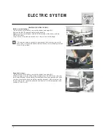
Page 168: ...g the bleed operation the fluid level inside the reservoir m ust never be low er than the m inim um level As the braking fluid is a very corrosive substance in the case it com es in contact w ith your eyes w ash them abundantly w ith w ater During the bleeding of the braking circuit keep the handlebar turned leftw ards This is the w ay to lift pum p tank and to m ake easier the bleeding of the bra...

Page 169: ...t for a few seconds before repeating the operation until only fluid com e out of the tube Close the bleed union to the prescribed torque and check the fluid level A inside the reservoir before replacing the cap If the bleeding operation has be done correctly the pedal will have no m ushy feel If not repeat the operation During the bleed operation the fluid level inside the reservoir m ust never be...

Page 170: ...o replace the fluid proceed as follows Rem ove the rubber cap on the bleeding valve 1 or 1A Attach a clear plastic hose to the bleeding valve on the brake caliper and turn the other end of the hose into a container Rem ove fluid reservoir cap 2 or 2A and the rubber Loosen bleeding valve on the brake caliper Pum p with brake lever 3 or brake pedal 3A in order to push brake fluid out of line Close t...

Page 171: ...9 BRAKES Periodically check the connecting hoses A and B if the hoses are worn or cracked their replacem ent is advised ...

Page 172: ...10 ...

Page 173: ...1 ELECTRIC SYSTEM Section ...

Page 174: ...fier check M 11 STARTER SYSTEM M 12 Starter m otor disassem bly M 13 Starter m otor check M 13 Electric start rem ote control sw itch check M 15 ELECTRONIC IGNITION SYSTEM M 16 Electronic coil resistance check M 17 Electronic pow er unit M 18 Voltage regulator rectifier M 18 Spark plug M 19 Neutral position sensor M 19 Carburetor throttle position sensor check TPS M 20 BATTERY M 21 Battery recharg...

Page 175: ...HANDLEBAR COM M UTATORS M 44 R H com m utator TE SM M 44 L H com m utator TE SM M 45 ARRANGEM ENT OF W IRING HARNESS ON THE FRAM E M 46 NOTES M 47 Connectors M 47 Couplings M 47 Fuses M 48 Sem iconductors parts M 48 Battery M 49 LOCATING OPERATING TROUBLES M 50 TAIL LAM P M 43 ...

Page 176: ...4 ELECTRIC SYSTEM ...

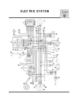
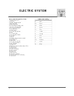
Page 177: ...ators flasher 15 Tail light 16 Battery 17 Electric start rem ote control switch 18 Starting m otor 19 Spark plug 20 R H rear turn indicator 21 L H rear turn indicator 22 Neutral switch 23 Ignition coil 24 Carburetor throttle position sensor TPS 25 Speed sensor 26 Ignition switch 27 Clutch m icroswitch 28 Therm oswitch 29 Electric fan 30 Safety switch 31 Fuel level resistance 32 Electronic power un...

Page 178: ...nd the cylinder Electric start rem ote control switch 8 on the left side of the fram e at the back of the panel Headlam p 11 with two filam ents bulb of 12v 35 35W TE 12v 55 60W SM and parking light bulb of 12V 3W TE 12v 5W SM Rear tail light 12 with stop bulbs of 12V 21W and parking light bulb of 12V 5W Therm istor 13 Flash device 16 on the right side of the fram e at the back of the panel Turn s...

Page 179: ...7 ELECTRIC SYSTEM ...

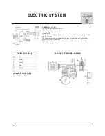
Page 180: ...or rectifier into DC current The regulator rectifier prevents overcharging of the battery and changes the AC current to the DC current All these com ponents m aintain a constant voltage and prevent the battery from overcharging CHARGING SYSTEM W IRING DIAGR AM Cable color coding Bk Black G Green Y Yellow R Red W W hite For the key to electrical com ponents see the w iring diagram page M 4 ...

Page 181: ...ed for long periods for m ore than one m onth and a half it is recom m ended to rem ove battery from electrical system and store it in a dry place Regulated voltage To gain access to the battery rem ove the saddle see page E 4 W hen the engine is warm and working at slightly m ore than 3000 rpm m easure the tension between the two battery term inals positive and negative with a tester in order to ...

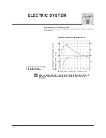
Page 182: ...arness connector then check the continuity using a tester Generator no load voltage perform ances 1 Secondary no load voltage 2 Charging current 3 Rotational frequency EVERY ENGINE OVERHAUL CLEAN THE FLYW HEL ROTOR REM OVING ANY DEBRIS G ATHERED IN CENTRIFUG ATED OIL AND ATTR ACTED TO THE M AGNETS ...

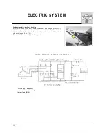
Page 183: ... the engine if the battery tension does not increase 14 5V after about four m inutes substitute the regulator To access the regulator rem ove the seat and side panel pages E 14 E 21 Rem ove the fixing screws 1 and the regulator VOLTAGE REGULATOR RECTIFIER W IRING DIAGR AM For the key to electrical com ponents see the w iring diagram page M 4 ...

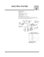
Page 184: ...itch 27 Pull the clutch lever until the engine starts Pressing the starting switch the button energizes the electric start rem ote control switch causing the contact points to close and com pleting the starter system circuit from the starting m otor to the battery Cable color coding B Blue Bk Black G Green O Orange R Red W W hite For the key to electrical com ponents see the w iring diagram page M...

Page 185: ...necessary to proceed as follows with the check connect a tester between earth and the starter m otor term inal check that there is continuity between the positive pole and the engine earth If there is no continuity substitute the starter m otor Apply a sm all quantity of LOCTITE 243 to the bolts of the starter m otor Starter m otor Nom inal voltage 12V Absorbed power 700 W Free running check Volta...

Page 186: ... 5 Load current Starter m otor m aintenance M aintenance operations on the starter m otor involve checking the brushes for wear that the stator and rotor do not touch and that they are correctly insulated It is advisable to carefully lubricate the m otor s m oving parts with AGIP F 1 GREASE grease ...

Page 187: ...m inals 1 and 2 of the relay and check the conti nuity between term inals B M Do not apply the battery voltage to the starter relay for m ore than five sec onds to avoid overheating and therefore dam aging the w inding Using a m ulti tester check that the winding is on open circuit or if a resistance is present The winding is in good condition if the value of the resistance revealed is as indicate...

Page 188: ...NGINE r p m CARBURETOR THROTTLE VALVE POSITION SENSOR ENGAGED GEAR This system allows to optim ize the engine perform ances in every condition of em ploym ent In case of throttle valve or transm ission gear failure the ignition is able to allow the use of the m otorcycle however The electronic ignition system consists of page M 23 Electronic power unit 1 Alternator 2 Voltage regulator rectifier 3 ...

Page 189: ...resistance 5 0 7 5 KOhm a 20 C without spark plug cap cable 10 0 12 5 KOhm a 20 C with spark plug cap cable If the resistance is not between the specified values replace the electronic coil Also check the resistance of the term inal cap contact with the spark plug Term inal cap resistance 4 5 5 5 KOhm a 20 C If the resistance is not between the specified values replace the electronic coil NOTE The...

Page 190: ... W IRING DIAGR AM VOLTAGE REGULATOR RECTIFIER W IRING DIAGR AM Voltage regulator rectifier The voltage regulator rectifier 1 contains the diodes to rectify the current produced by the generator It contains also an electronic device operating in relation to the battery tension if battery has a low charge recharge current will be high on the contrary if battery will be charged the current will be lo...

Page 191: ...e color of the insulator provide useful indications concerning the heat rating of the plug carburetion ignition and general engine condition Before refitting the plug thoroughly clean the insulator using a brass m etal brush Apply a little graphite grease to the plug thread fit and screw the plug hom e by hand and then tighten to the correct torque 10 12 Nm 1 0 1 23 Kgm 7 2 8 9 ft lb using a plug ...

Page 192: ...osition sensor cable 1 from the m ain wiring harness Set the two tester term inals in correspondence of YELLOW A and BLACK B cables and check for the correct values see table A Yellow B Black Fig 1 throttle control grip in CLOSED position 890 990 Fig 4 throttle control grip in COM PLETELY OPEN posi tion 3 4 4 4 K 5 ...

Page 193: ...oltm eter that battery voltage is not less than 12 5 V If not the battery needs to be charged Using a battery char ter with a constant voltage first connect the RED positive cable to the battery s positive term inal then the BLACK negative cable to the battery s negative term inal Apply to the constant voltage of 14 4 V a current of x Am pere as results in the below diagram depending on the am oun...

Page 194: ...Service Coupon B 6 M AX ENGINE r p m warning light the warning light com es on after that the vertical and horizontal LED indicators have com pleted their stroke 8250 r p m approx 7 GREEN warning light Blinkers 8 BLUE warning light High beam 9 AM BRE warning light Fuel reserve 3l 2 6 Im p Qt 3 2 U S Qt 10a Vertical LED indicator BATTERY CHARGE the indicator is on when the ignition key is on IGNITI...

Page 195: ...ch is the active units Press and release the M ODE button to change from Km h to M ph vise versa Press and hold the M ODE button until W S re appears to accept your selection Setting oil change w arning interval 9 Press and release the M ODE button until you see the oil change sym bol fig 11 Press and hold M ODE button until the horizontal bars appear not shown then release You are presented with ...

Page 196: ... RPM screen hold the M ODE button until W S appears The RPM screen will be rem oved and the battery m eter will be displayed on all screens fig 11 To restore the RPM graph restore all screens and cycle the screens until the RPM screen is displayed Screen Effect Hold till W S Hold till horizontal bars see fig 9 Odom eter fig 1 Restores all other screens N A Trip Odom eter fig 2 Rem ove screen N A A...

Page 197: ...25 ELECTRIC SYSTEM Fig 1 Fig 2 Fig 3 Fig 4 Fig 5 Fig 1 Fig 7 Fig 8 Fig 9 Fig 10 Fig 6 Fig 12 Fig 11 ...

Page 198: ...cem ent M odel TE rem ove the four elastic 1 fig 1 and rem ove the headlam p holder 2 M odel SM rem ove the screw 3 fig 2 and the headlam p holder Rem ove the two fixing nuts 4 fig 3 disconnect the connector 5 and rem ove the instrum ent ...

Page 199: ...a height which is so greater than 9 10 of the height from the ground of the centre of the headlam p TE adjust the headlam p aim ing by turning screw 6 to lower or lift the high beam SM unscrew the 2 screws 7 and adjust the headlam p to lower or lift the high beam Headlam p bulbs replacem ent TE SM To gain access to the headlam p bulbs proceed as follows TE rem ove the four fastening elastics 1 and...

Page 200: ...ulb 12V 5 21W proceed as follows rem ove the two fastening screws 1 and the rear lens 2 push the bulb 4 and turn it counterclockwise extract the bulb from holding inner cover 3 and replace it After replacem ent reverse operations for reassem bly M ake sure not to tighten the screws excessively ...

Page 201: ...low GR Grey N Black R Red R N Red Black V Green V B Green W hite V N Green Black Cable color coding Az Sky blue BL N Blue Black TE SM HANDLEBAR COM M UTATORS M easure the com m utators continuity using a tester In case of anom alies replace the defective part R H COM M UTATOR ...

Page 202: ...30 ELECTRIC SYSTEM TE SM L H COM M UTATOR ...

Page 203: ... IRING HARNESS ON THE FRAM E 1 in order to facilitate the tank and saddle assem bling hold downward the sheath 2 M ake attention to correctly positioning the connector rubber of the instrum ent Assem ble the clam ps as shown in the figure ...

Page 204: ...e the BLACK negative cable then the RED positive cable when reassem bling first connect the RED positive cable then the BLACK negative cable LOC ATING OPERATING TROUBLES CHARGING SYSTEM Fast battery discharging 1 current leakage see page M 9 2 incorrect voltage see page M 10 3 generator no continuity see page M 10 4 incorrect generator no load voltage perform ances see page M 11 5 faulty voltage r...

Page 205: ...1 ENGINE COOLING SYSTEM Section ...

Page 206: ...rly that is that the electric fan rem oves the warm air from the radiator Check of radiator level m ust be perform ed with cold engine see page D 15 If for any reason you have to operate on a hot engine take care to slowly discharge pressure The radiator cap is provided of two unlocking positions the first being for the previous pressure discharge Opening the circuit w ithout taking care of above ...

Page 207: ...oval of these obstructions taking care not to dam age radiator If distortions are noticed it is advisable to straighten them so restoring the air passage The radiant m ass has not to be clogged or dam aged for m ore than 20 of its surface If the dam aged surface is over this lim it it shall be advisable to replace radiator Periodically check the connecting sheats this will avoid water leakages and...

Page 208: ...4 ...

Page 209: ...1 LUBRICATION CIRCUIT Section ...

Page 210: ...side when it passes through the double screen filter and re turns to the delivery pum p A vent fitting on the cylinder head deliv ers oil vapors in the fram e upper beam where take place the separation of the oil from the vapors conveyed respectively A In the engine block through a fitting connected to the fram e B In the air filter box through a pipe A lam ination valve located behind the distrib...

Page 211: ...1 SPECIFIC TOOLS Section ...

Page 212: ...ler 5 8000 39524 Clutch hub retaining 6 1519 84701 Spring hook 7 8000 39522 Flywheel disassem bling wrench 8 8C00 52306 Piston assem bling tool 9 8000 90611 Crankshaft bearing puller 10 8000 83254 Crankshaft guard 11 8000 90674 Ignition assem bling tool 12 8000 39521 Valves assem bly and reassem bly tool 13 8000 90875 T D C control tool ...

Page 213: ... cause them to becom e dam aged or loose leading to vehicle dam age or injury to the rider Over tightening a nut or bolt can strip its thread or cause breakage The table shows the torque settings for the m ain nuts and bolts in relation to thread diam eter pitch and use The above torque settings refer to threads which have been cleaned with solvent ...

Page 214: ...TITE 243 20 Nm 2 Kgm 14 5 ft lb Prim ary drive driving gear fastening nut M 24x1 25 100 Nm 10 2 Kgm 73 8 ft lb Tim ing chain tensioner fastening screw M 6x1 4 5 Nm 0 46 Kgm 3 3 ft lb Tim ing chain slider fastening screw M 8x1 25 12 Nm 1 23 Kgm 8 9 ft lb Tim ing chain spring fastening plug M 6x1 5 Nm 0 5 Kgm 3 6 ft lb Engine oil valve fastening screw M 4x0 7 LOCTITE 243 3 Nm 0 3 Kgm 2 2 ft lb Oil s...

Page 215: ...10x1 M OLIKOTE HSC 12 Nm 1 23 Kgm 8 9 ft lb Flywheel Rotor Free wheel outer ring fastening screw M 6x1 LOCTITE 601 20 Nm 2 Kgm 14 5 ft lb Clutch hub and disc housing fastening nut M 18x1 61 7 Nm 6 3 Kgm 45 6 ft lb Clutch hub and disc pressure plate fastening screw M 6x1 10 Nm 1 Kgm 7 2 ft lb Gear shift sprocket plate fastening screw M 6x1 10 Nm 1 Kgm 7 2 ft lb Gearbox forks driving shaft fastening...

Page 216: ...19 Nm 1 95 Kgm 14 ft lb Rear brake pedal adjusting cam fastening screw M 6x1 14 7 Nm 1 4 Kgm 10 8 ft lb Front brake hose guide plate fastening screw M 6x1 6 Nm 0 6 Kgm 4 4 ft lb Front fork legs fastening screw M 8x1 25 25 Nm 2 5 Kgm 18 4 ft lb Steering bearings adjusting ring nut M 25x1 3 45 Nm 0 35 Kgm 2 5 ft lb Steering pivot fastening nut M 24x1 83 3 Nm 8 5 Kgm 61 4 ft lb Handlebar upper clam p...

Page 217: ...d fastening screw M 6x1 6 Nm 0 6 Kgm 4 4 ft lb Side panel fastening screw M 6x1 6 Nm 0 6 Kgm 4 4 ft lb Rear reflector fastening nut M 4x0 7 1 9 Nm 0 2 Kgm 1 4 ft lb Turn signals fastening screw M 6x1 6 Nm 0 6 Kgm 4 4 ft lb Front headlam p fastening screw TE ø 3 9 1 45 Nm 0 15 Kgm 1 ft lb Front headlam p fastening screw SM M 6x1 6 Nm 0 6 Kgm 4 4 ft lb Electric start rem ote control switch cables fa...

Page 218: ...4 Nm 0 45 Kgm 3 2 ft lb Rear wheel sprocket fastening nut M 8x1 25 LOCTITE 243 34 3 Nm 3 5 Kgm 25 3 ft lb Rear wheel axle fastening nut M 20x1 5 142 1 Nm 14 5 Kgm 104 8 ft lb Drive sprocket cover fastening screw M 6x1 10 4 Nm 1 Kgm 7 7 ft lb Exhaust silencer fastening screw M 6x1 10 4 Nm 1 Kgm 7 7 ft lb Exhaust pipes to cylinder head fastening screw M 6x1 10 4 Nm 1 Kgm 7 7 ft lb Instrum ent fasten...

Page 219: ...1 FRAME AND W HEELS Section ...

Page 220: ... heel Y 4 Rem oving the front w heel Y 5 Reassem bling the front w heel Y 5 Rear w heel Y 6 Rem oving rear w heel Y 7 W heels overhauling Y 8 Bending the w heel pin Y 8 W heel spokes Y 8 Rim s w arpage Y 9 Rear sprocket transm ission sprocket rear chain Y 9 ...

Page 221: ...cated enable to see if the fram e should be realigned or replaced The fram es seriously dam aged should be replaced AXIS X Y A 136 5 35 85 3 35 B 373 6 14 71 25 1 C 320 2 12 6 396 9 15 62 D 354 6 13 96 407 4 16 04 E 319 6 12 58 453 7 17 86 F 488 19 21 556 9 21 92 G 633 24 92 398 3 15 68 H 18 7 0 74 352 1 13 86 I 95 3 74 349 5 13 76 L 8 0 31 81 3 19 STANDARD m m in steering axis angle 29 ...

Page 222: ...nd dim ension TE M etzeler M CE KAROO Pirelli M T 21 90 90x21 SM Pirelli M TR 21 DIABLO Dunlop D208 F 120 70 17 Cold tire pressure front SM Road use driver only 25 6 psi front SM Road use driver and passenger 28 4 psi front SM Racing use driver only 20 psi front TE Road use driver only 17 1 psi front TE Road use driver and passenger 21 3 psi front TE Racing use driver only 14 2 15 6 psi Front w he...

Page 223: ... wheel between the front fork legs Fit the wheel axle 2 from the R H side after greasing it and push it to the stop on the L H leg during this operation the wheel should be turned Tighten the screw 3 on the fork L H side but DO NOT lock it Now pum p for a while pushing the handlebar downwards until you are sure that the fork legs are perfectly aligned Lock the screws 1 on the R H leg 10 4 Nm 1 05 ...

Page 224: ...lloy 4 25x17 Tire m ake type and dim ension TE M ichelin ENDURO COM P 3 Pirelli M T 83 Scorpion Dunlop 54RD907 120 90x18 250 140 80x18 450 510 TC Pirelli NHS 62 M T 32 100 90x19 250 110 90x19 450 510 SM R Pirelli M TR 22 DRAGON EVO 150 60x17 Cold tire pressure TE TC 0 8 0 9 Kg cm 2 11 4 12 8 psi Cold tire pressure SM R 1 6 kg cm 2 22 7 psi Racing use 2 0 kg cm 2 22 7 psi Road use rider only 2 2 kg...

Page 225: ...com plete rear wheel by taking care of the spacers located at the hub sides To reas sem ble reverse the above procedure rem em bering to insert the disc into the caliper NOTES Do not operate the rear brake pedal when the wheel has been rem oved this causes the caliper piston to m ove outwards After rem oval lay down the wheel with brake disc on top After reassem bly pum p the brake control pedal u...

Page 226: ...ad exercising pressure only on the bearing outer ring to com plete inserting Place the spacer and the proceed with the placing of the other bearing Check their alignm ent by placing the wheel pin After every intervention on wheels their balancing is advisable W heel axle bending If the bending figure is over the allowable m ax lim it straighten or replace the axle If the axle can not the straighte...

Page 227: ...it Side skid less than 0 019 in 0 2 m m 0 0078 in W heel out of true Eccentricity less than 0 031 in Rear sprocket transm ission sprocket and drive chain The figure shows the outline of teeth in norm al and excessive wear Should the sprocket be badly worn out replace it by loosening the six fastening screws to the hub After every rear sprocket replacem ent also replace the drive sprocket and trans...

Page 228: ...st pin center Check the pinion dam ages or wear and replace it should the wear degree be as the one shown in figure M isalignm ent of the wheel will result in abnorm al wear and m ay result in an unsafe riding condition In m uddy and wet conditions m ud sticks to the chain and sprockets resulting in an over tight chain The pinion the chain and the rear sprocket wheel wear increases when running on...

Page 229: ...1 NOTES FOR USA CDN AUS MODELS Section ...
Page 230: ...f design has been rem oved or rendered inoperative by any person Am ong those acts presum ed to constitute tam pering are the acts listed below 1 Rem oval of or puncturing the m uffler baffles header pipes or any other com ponent which conducts exhaust gases 2 Rem oval or puncturing of any part of the intake system 3 Lack of proper m aintenance 4 Replacing any m oving part of the vehicle or parts ...

Reviews: