F2.5
Part. N. 8000 H4704 (07-2010)
04
05
MAINTENANCE
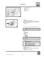
Direction "a": Valve clearance increases.
•
Direction "b": Valve clearance decreases.
•
Valve adjuster screw check nut: 7 Nm (0.7 mkg,
•
5.1 ft-lb)
06
Adjust:
4.
Valve clearance
•
Loosen check nut "
a.
1
" .
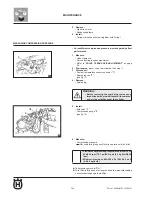
Fit the blade of a feeler gauge "
b.
2
" in-between the adjuster screw
end and the valve stem tip. (see fig. 05)
Turn adjuster screw "
c.
3
" in direction "
a
" or "
b
" until obtaining the
specified valve clearance. (see fig. 06)
Hold the adjuster screw in place and tighten the check nut as
•
specified.
Measure valve clearance again.
d.
If valve clearance still does not meet the specifications, repeat
e.
all valve clearance adjustment steps until obtaining correct
clearance.
Measure valve clearance using a feeler gauge. (see fig.04)
d.
Not conforming to specs
Adjust.
Summary of Contents for SMS4
Page 1: ...Workshop Manual TE 125 2011 SMS4 2011 Part N 8000H4704 07 2010 ...
Page 6: ......
Page 7: ...A 1 A Part N 8000 H4704 07 2010 GENERAL INFORMATION Section ...
Page 14: ......
Page 15: ...b 1 Part N 8000 H4704 07 2010 b IMPORTANT NOTICES Section ...
Page 17: ...F 1 Part N 8000 H4704 07 2010 TECHNICAL DATA F Section ...
Page 35: ......
Page 36: ......
Page 37: ...F1 1 Part N 8000 H4704 07 2010 F1 ENGINE OVERHAUL Section ...
Page 109: ...F2 1 Part N 8000 H4704 07 2010 F2 MAINTENANCE Section ...
Page 121: ...F3 1 Part N 8000 H4704 07 2010 F3 ENGINE COOLING Section ...
Page 131: ...F4 1 Part N 8000 H4704 07 2010 F4 CARBURETTOR Section ...
Page 132: ...F4 2 Part N 8000 H4704 07 2010 CARBURETTOR CARBURETTOR ...


