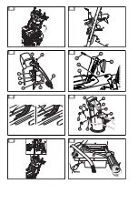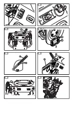
2. Raise the drive speed control lever (C) from the
middle position to make the product move
forward when the drive engagement (B) is
engaged.
3. Lower the drive speed control lever from the
middle position to make the product move
rearward when the drive engagement is
engaged. (Fig. 66)
4. To make the product move in the selected
direction, hold the drive engagement against the
handle .
5. If the product has power steering, hold the left
steering trigger (D) to turn left. Hold the right
steering trigger to turn right. (Fig. 67)
Throttle control
Note:
If the snow is wet or heavy, use the fast or
boost modes.
The throttle control adjusts the engine speed. It has
3 modes: boost, fast and slow.
(Fig. 68)
• Boost (A): to increase speed when the product is
operated but does not throw snow, or to increase
the distance that snow is thrown.
• Fast (B): standard operation
• Slow (C): to decrease the distance that snow is
thrown, or to decrease engine noise
To use the throttle control
• Turn the throttle control to change the engine
speed.
To use the heated handles
• Push the switch to I to start the heated handles.
• Push the switch to O to stop the heated handles.
(Fig. 69)
To stop the product
1. Turn the key to the STOP position. (Fig. 70)
2. Remove the ON/OFF key.
To adjust the discharge chute and
the discharge chute deflector
1. Push the release lever (B) on the discharge
chute lever (A) and adjust the discharge chute to
the left or right position. (Fig. 71)
2. Move the remote control lever (C) to adjust the
snow throwing distance.
a) Move the remote control lever up to decrease
the snow throwing distance.
b) Move the remote control lever down to
increase the snow throwing distance.
To adjust the skid plates
The skid plates prevent damage to the bottom of the
snow thrower. Adjust the skid plates (A) when the
locknut (B) is loose, or the skid plate is not at the
correct distance from the ground. No adjustment is
necessary for standard installation.
1. Loosen the locknut (B) with a 13 mm (½ in.) open
wrench.
2. Move the skid plates (A) up or down.
a) On flat surfaces set the distance between the
scraper bar and the ground to 5-6 mm
(0.2-0.25 in).
b) On rough surfaces set the skid plates (A) in a
position where the scraper bar is above the
top of the ground.
WARNING:
Make sure that
gravel and stones do not go into
the product. Objects that eject at
high speed can cause injury.
3. Tighten the locknut (B). (Fig. 72)
To use the drift cutters (if equipped)
Use the drift cutters to cut through snowdrifts deeper
than the front of the product.
1. Loosen the adjustment nuts (A) on both sides of
the product to allow each drift cutter (B) to be
raised to its highest position. (Fig. 73)
2. Tighten the nuts.
3. Lower the drift cutters after use.
To adjust the height of the auger
bucket (for ST 424T/427T/430T only)
1. Push the lever (A) down. (Fig. 74)
2. Move the handles (B) up or down to adjust the
height of the auger bucket .
3. Release the lever (A) to lock the auger bucket in
position.
Note:
The auger bucket can be set to an unlocked
position. This lets the auger bucket adapt to the
terrain. To set the auger bucket to the unlocked
position, push the lever (A) down and to the right.
To prevent freeze-up after use
Note:
Controls and moving parts can be blocked
by ice. Do not apply much force to the controls. If
you cannot operate a control or a part, start the
engine and let it operate for some minutes.
1. Start the engine and let it operate for some
minutes. Stop the engine and wait for all moving
parts to stop.
2. Remove snow and loose ice from the product.
876 - 014 - 19.05.2021
17
Summary of Contents for ST 424T
Page 4: ...53 A B C 54 A B E F D C G J I H 55 C E F A B D 56 57 F L M B A D K C E G 58 B A C 59 60 ...
Page 5: ...61 62 63 B A C D 64 A 65 C B 66 D 67 A B C 68 ...
Page 6: ...69 70 C A B 71 B A 72 A B 73 B A 74 A 75 D C B A 76 ...
Page 7: ...A 77 B A 78 79 A B D B C 80 B C A D 81 A B C D 82 A 83 B A C 84 ...
Page 8: ...C A B 85 A B C D E 86 B A 87 A E B D C 88 A F E B D C 89 A G F E B D C 90 B A 91 B B D 92 ...


