English –
45
Symptom
Possible causes
Recommended actions
Product cannot be activated. No
LED´s light up when pressing the
on/off button.
Broken battery
1. Check battery by pressing the
status button. Minimum 1 green
LED should be visible. See also
Battery and Charger
Bad connection between battery and
product
2. Make sure power connectors
between battery and product are
not damaged and free from dirt.
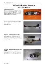
See pic. 1 in appendix.
Bad connection in keypad connector
3. Make sure the keypad connec-
tor is properly assembled, dry, not
damaged and free from corrosion.
See pic. 2 in appendix.
Broken keypad
4. Replace keypad
Damage to multiwire cable between
control unit and keypad/trigger switch
5. Repair/replace multiwire cable.
(Only if visible damage is present)
Broken control unit
6. Replace control unit
Product cannot be activated and
destroys batteries that are inserted
Short circuit in control unit
Replace control unit
Electric motor does not react when
applying the trigger
Bad connection in trigger switch signal
connector
1. Make sure the trigger switch
signal connector is properly as-
sembled, dry, not damaged and
free from corrosion. See pic. 3 in
appendix
Motor connector not correctly assem-
bled
2. Make sure the motor
connector(s) are correctly assem-
bled. See pic. 4 in appendix.
Internal damage to trigger switch
3. Replace trigger switch
Short circuit in control unit
4. Replace control unit
Electric motor jerks shortly when
applying the trigger, then stops
Short circuit in control unit
Replace control unit
Product shuts off when applying
load
Bad connection between battery and
product
Make sure power connectors bet-
ween battery and product are not
damaged and free from dirt. See
pic. 1 in appendix.
Keypad lights flicker
Bad connection in keypad connector
1. Make sure the keypad connec-
tor is properly assembled, dry, not
damaged and free from corrosion.
See pic. 2 in appendix.
Short circuit in keypad
2. Replace keypad
Unstable motor speed
Bad connection in trigger switch signal
connector
1. Make sure the trigger switch
signal connector is properly as-
sembled, dry, not damaged and
free from corrosion. See pic. 3 in
appendix
Damaged or worn trigger switch
2. Replace trigger switch
10 Troubleshooting - T536 LiXP
S/N – 2015100001
Troubleshooting
Summary of Contents for T536 Li XP
Page 1: ...Workshop Manual English T536 Li XP ...
Page 2: ......
Page 5: ......
Page 55: ......
Page 56: ... 115 53 98 26 2015W36 ...


