M.19
TE 250 - 310 2012 I.E. / TE 250 - 310 2012 I.E. USA
TC 250 2012 - TC 250 2012 I.E. USA
TXC 250 - 310 2012 I.E. USA
TE
H10112
38
40
39
1
2
3
4
5
6
7
8
9
10
11
12
13
14
34
35
36
31
32
33
18
17
16
15
19
20
21
22
23
24
25
26
27
28
29
30
37
ELECTRICAL SYSTEM
Workshop Manual Ed. 12-2011
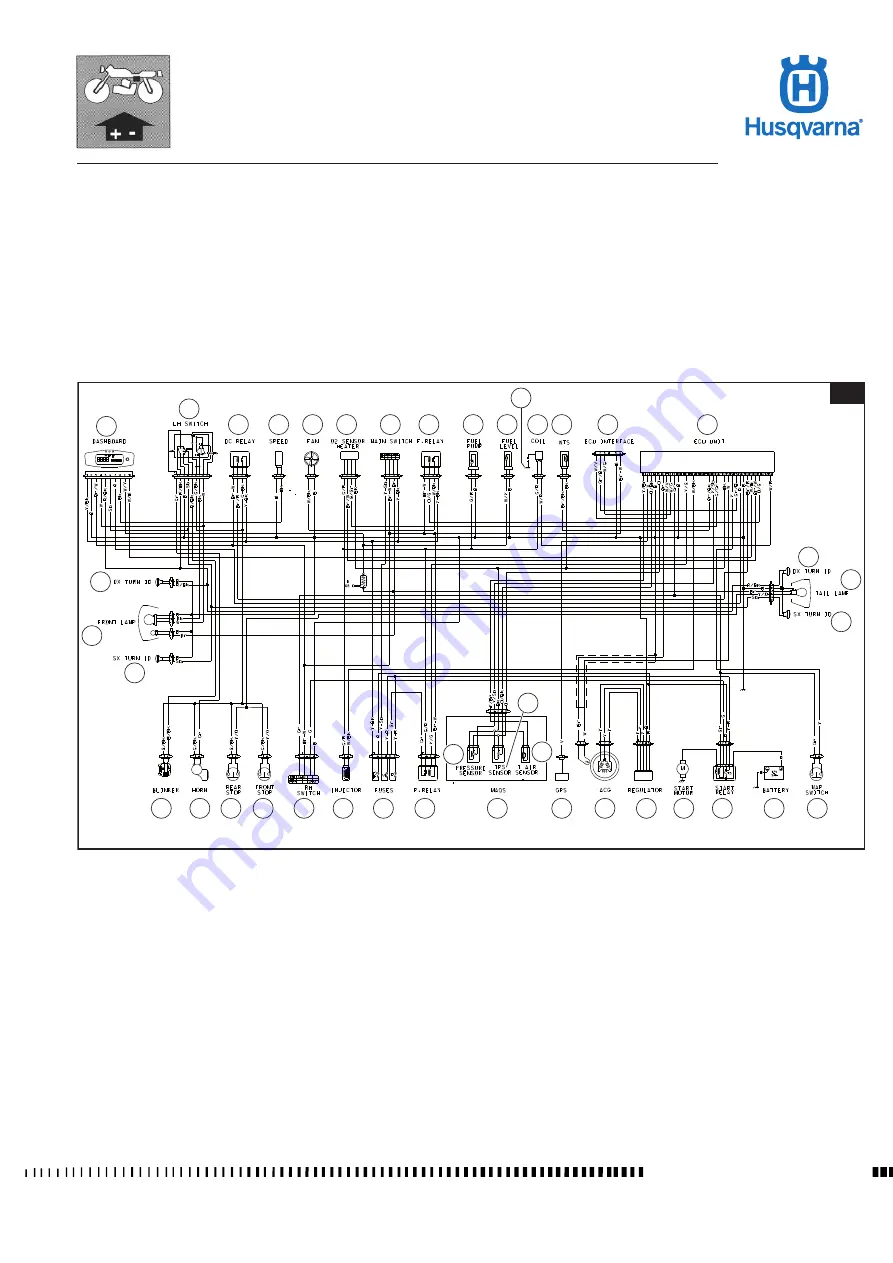
Ignition and starter system (TE-TXC)
The engine injection and starter system is controlled by the control unit (ECU);
by means of a series of sensors, the ECU controls the status of the engine and
of the surrounding environment at each given moment.
The sensors are: a crankshaft position sensor (pick-up), a temperature sensor
of the filter box ambient air, and a group of sensors (MAQS) on the throttle body
that provide information about pressure, air temperature, and position of the
throttle opening.
Moreover, the ECU uses a lambda probe for the constant adjustment of the air-
fuel ratio (Euro3 mode)
Key
1. Electronic control unit
2. Control unit interface
3. Coolant temperature sensor
4. HT coil
6. Fuel pump
7. Electric fan relay
8. Ignition switch
9. Lambda sensor
10. Cooling fan
12. DC relay
13. L.H. switch
16. Battery
17. Solenoid starter
18. Starter motor
19. Voltage regulator
20. Alternator
21. Gear sensor
22. M.A.Q.S. (38+39+40)
23. Power relay
24. Fuses
25. Injector
26. R.H. switch
37. Spark plug
38. Pressure sensor (22)
39. Throttle position sensor (22)
40. Air temperature sensor (22)


