

English
–
5
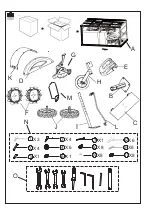
References
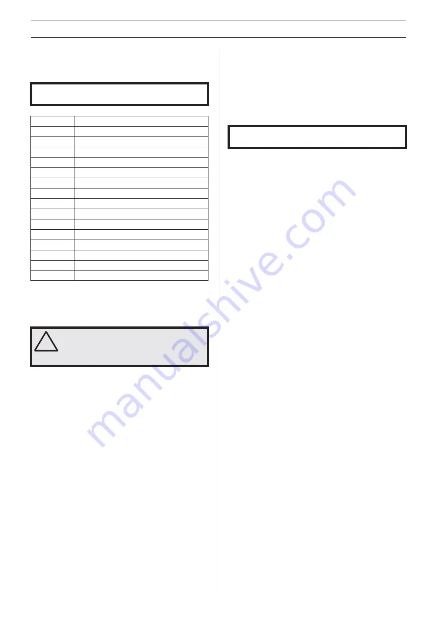
Content of the case
A
Engine parts
B
Wheel axle
C
Back tine cover
D
Side cover, R
E
Handlebar cover
F
Iron wheel
G
Tine assy, R
H
Rear wheel
I
Drag bar
J
Wheel
K
Tine cover
L
Shifting lever
M
Tidy cover
N
Hardware bag
O
Tool bag
!
ASSEMBLING AND ADJUSTMENTS
Unpacking
Illustration: 1 • 1
IMPORTANT! Make sure to not cut the cables or scratch the
machine when cutting the edges of the case.
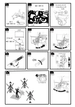
• Adjust the height of the handle by engage
the right lever.
(Figure 13)
• Fitting the clutch control.
(Figure 14)
- Turn to proper side and fasten the bolt.
Any dismantling operation must only be performed by an
authorized service workshop.
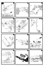
Assembly
Illustration: 1 • 2
WARNING! Inappropriate assembly of this
rotary tiller could cause severe injuries.
Ensure that you follow all the instructions
carefully.
• Fitting the handlebar.
(Figure 1)
• Fitting the wheels.
(Figure 2)
• Fitting the tine cover.
(Figure 3)
• Fitting the right tine assy.
(Figure 4)
• Fitting the side cover.
(Figure 5)
• Fitting the drag bar and support wheel.
(Figure 6)
• Fitting the back cover.
(Figure 7)
• Fitting the shifting lever.
(Figure 8)
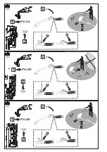
• Fitting the PTO lever.
(Figure 9)
• Fitting the handlebar cover.
(Figure 10)
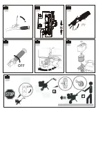
• Fitting the tidy cover.
(Figure 11)
• Tidy the cables.
(Figure 12)
CAUTION! After assembling the machine completely, tighten
the bolts and screws with moderation. Do not overtighten.
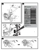
Description of the components
Illustration: 1 • 3
1 Engine
2 Bumper
3 PTO lever
4 Shifting lever
5 Handlebar
6 Throttle control
7 Drag bar
8 Tine cover
9 Tine
10 Iron wheel
11 ON/OFF switch
12 Lever for handle height adjust
13 Clutch control
Type plate
Illustration: 1 • 4
1 Serial number
2 Article number
3 Tilling scope
4 Gear shifting
5 Engine displacement
6 Engine oil Quality (viscosity):
7 Engine oil capacity
8 Gear box oil quality
9 Gear box oil capacity
10 Nominal power
11 Net weight
12 Fuel
Transport wheel
Illustration: 1 • 5
Change the cultivator from working status to transporting
status. Change the iron wheel to tyre, assemble the rear
wheel.
- Put the cables through the holding spring.
- Fit the cables in cable clip.
For more information about moving of the machine, see
section "Moving".
Summary of Contents for TR262
Page 3: ...3 1 3 2 1 2 2 3 12 4 4 5 6 2 3 12 7 8 9 5 6 7 10 2 1 1 1 1 ...
Page 4: ...13 14 ...
Page 5: ...1 3 11 6 12 13 1 4 5 4 7 2 3 1 8 9 10 1 5 ...
Page 7: ...2 3 A B 3 1 2 3 A B 3 2 2 3 A B 3 3 1 PTO ON 1 PTO OFF 1 PTO OFF ...
Page 8: ...4 4 4 5 4 6 OFF 5 1 OFF A B 4 1 N 4 2 4 3 ...
Page 41: ......
Page 42: ......
Page 43: ......


