

15
KEY PART DESCRIPTION
NO. NO.
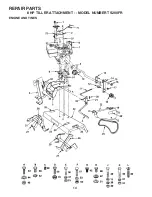
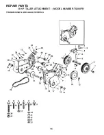
REPAIR PARTS
8 HP TILLER ATTACHMENT - - MODEL NUMBER TS200FR
ENGINE AND TINES
KEY PART DESCRIPTION
NO. NO.
1 124533X Control Throttle
2 6924J Bracket, Throttle Control
3 677A860 Hitch Yoke Assembly
4 4379H Grip, Handle
5 677A855 Hitch Channel Assembly
6 6922R Plate, Adapter
7 - - - - - - - Engine 8 H.P., Tecumseh
8 104867X Decal, In struc tion, Engine
9 4914H Square Key 1/4 x 1-1/4
10 8249R Engine Sheave
11 6652H Belt Tightener Link
12 6656H Adjusting Pin
13 624A12 Idler Support Plate and Pivot
14 2360J Idler Arm
15 19151116 Washer 15/32 x 11/16 x 16 Ga.
(0 - 2 as required)
16 12000015 * E-Ring
17 6683H E-Ring
18 4933H Idler Pulley
19 19131414 Washer 13/32 x 7/8 x 14 Ga.
20 4497H Clip, Hairpin
21 626A430 Lever and Arm
22 634A726 Belt Guard and Supports
24 102655X V-Belt
25 120076X Decal, Caution
26 4929H Drilled Pan Hd. Rivet 3/8 x 1-3/4
27 3146R Clip, Hairpin
28 626A401 Tine Weldment, L.H.
29 174043 Decal, On/Off
30 71180512 Screw, Fl. Hd. Mach. 5/16-24
31 626A402 Tine Weldment, R.H.
32 8224R Tine Shield
33 76020516 Cotter Pin 5/32 x 1
34 8905R Spring
35 76020824 Cotter Pin 1/4 x 1-1/2
36 74760516 * Bolt, Hex 5/16-18 x 1 Gr. 2
37 19131311 Washer 13/32 x 13/16 x 11 Ga.
38 10040600 * Washer Lock, Hvy. Hel. Spring
39 73220600 * Nut, Hex 3/8-16 UNC
40 74760524 * Bolt, Hex 5/16-18 x 1-1/2 Gr. 2
41 73220500 * Nut, Hex 5/16-18 UNC
42 15760512 Hex Bolt with Sems Ext. Washer
Lock 5/16-18 UNC x 3/4
43 74760416 * Hex Bolt 1/4-20 x 1
44 10040400 * Washer Lock 1/4
45 73220400 * Hex Nut 1/4-20 UNC
46 74770512 * Hex Bolt 5/16-24 x 3/4
47 10040500 * Washer Lock 5/16
48 23200506 Hex Socket Set Screw
5/16-18x3/8
49 74760624 * Hex Bolt 3/8-16 x 1-1/2
50 73750600 * Hex Lock Nut 3/8-16 UNC
51 19111116 * Washer 11/32 x 11/16 x 16 Ga.
53 19121214 Washer
52 11050500 Washer Lock External Tooth 5/16
67 72250614 Bolt, Carriage 3/8-16 x 1-3/4
69 71191008 Screw
70 73731000 Nut, Keps #10-24 UNC
71 4171R Clip - Insulated
72 168461 Decal, Throttle
- - 110719X Decal, Oper./Lubrication (Engine)
- - 104959X Decal, Tecumseh Logo (Engine)
- - 169689 Owner’s Manual, English
- - 169690 Owner's Manual, French
*STANDARD HARDWARE--PURCHASE LOCALLY
NOTE:
All component dimensions given in U.S. inches.
1 inch = 25.4 mm.


