background image

17

REPAIR PARTS

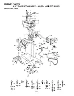
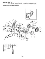
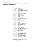
8 HP  TILLER ATTACHMENT - - MODEL NUMBER TS200FR

TRANSMISSION AND GAUGE WHEELS

  1    634A562          Transmission
  2    9135R              Retainer Spring
  3    4929H              Drilled Pan Head Rivet  3/8 x 1-3/4
  4    634A61             Gauge Wheel Sleeve and Brackets
  5    634A559           Gauge Wheel Adjusting Shaft and
                                 Bracket
  6    169374            Wheel
  7    4898H              Shoulder Bolt
  9    73560600         Locknut  3/8-16 UNC Nylock
10    5020J               Needle Bearing
12    4895H              Needle Bearing
13    9204 H             Locknut  1/2-20 UNF
14    4932H              Input Sheave
15    4910H              Oil Seal
16    3039R              Needle Bearing
17    4877H1            Gear Case Shield L.H.
18    634A553           Gear Case and Bearings L.H. Half
                                 (Inc. Key No's. 10,12,16 & 20)
19    2601R              Gasket
20    4870H             Thrust Cap
21    634A555          Tine Shaft and Sprocket
24    2600R              Roller Chain
26    1370H             Thrust Washer
27    4912H              Gasket
28    634A59             2nd Reduction Shaft and Gears
29    634A58             1st Reduction Shaft and Gears
30    9858M1           Woodruff Key  3/16 x 5/8
31    634A57             Input Shaft and Pinion
32    5855H              Relief Valve
33    6672H              Gear Shift Cover
34    4913H              Gasket
35    1685H              Locknut  5/16-18 UNC
36    13060400         Pipe Plug  1/2-14 N.P.T.
37    634A554           Gear Case and Bearings R.H. Half
                                 (Inc. Key No's. 12, 16 & 20)
38    4878H1            Gear Case Shield R.H.
39    10040600      * Washer Lock  3/8
40    73220600      *  Hex Nut  3/8-16 UNC
43    7850H              Spacer
44    19111116      * Washer  11/32 x 11/16 x 16 Ga.
45    74760636      *  Hex Bolt  3/8-16 x 2-1/4
46    17860524         Hex Hd. Roll-Lok Thd. Forming 

Screw  5/16-18 x 1-1/2

48    74760532      *  Hex Bolt  5/16-18 x 2
49    20000524         Flat Hd. Slotted Roll-Lok Thd.
                                 Forming Screws  5/16-18 x 3/4
50    74780596         Hex Bolt  5/16-18 x 6 Gr. 5
51    15760512         Screw Mach. Hex Hd.  5/16-18 x 3/4

KEY     PART            DESCRIPTION
NO.                   NO.

*STANDARD HARDWARE--PURCHASE LOCALLY

NOTE:

 All component dimensions given in U.S. inches. 

            1 inch = 25.4 mm.

Summary of Contents for TS 20

Page 1: ...OWNER S MANUAL 169689 Rev 2 4 11 03 TR Printed in U S A 8 H P 30 76 2 cm SLEEVE HITCH TILLER ATTACHMENT MODEL NUMBER TS200FR 02480 TS 20 ...

Page 2: ...this symbol to point out important safety precautions It means Attention Become Alert Your safety is involved Stop the engine motor when leaving the operating position before unclogging the tines and when making any repair adjustments and inspections Take all possible precautions when leaving the machine unattended Disengage the power take off lower the attachment shift into neutral stop the engin...

Page 3: ...A SPARK ARRESTERMEETINGAPPLICABLELOCALORSTATELAWS IF ANY IF A SPARK ARRESTER IS USED IT SHOULD BE MAINTAINED IN EFFECTIVE WORKING ORDER BY THE OPERATOR CONGRATULATIONS on your purchase of a new Til ler Attachment It has been designed engineered and manufactured to give you the best possible dependability and performance Should you experience any problems you cannot easily remedy please contact you...

Page 4: ... yoke of tiller Fig 2 Inset over hitch tube of sleeve hitch so that the hitch pin holes line up Insert hitch pin until it extends from bottom of hitch yoke Fig 2 Inset Insert retainer spring into hitch pin Tighten both stabilizer bolts against the hitch yoke until there is no looseness at the hitch point The frame assembly does not swing sideways relative to the hitch bail Fig 2 Be sure the frame ...

Page 5: ...ual Move tine clutch lever to ENGAGED position Dis engage and engage several times to check the clutch ing action of the belt Slowly lower tiller with tractor lift control and begin tractor forward movement Never operate tractor in reverse when tiller is in the ground To stop tiller and engine disengage tine clutch lever and move throttle lever to STOP position BEFORE STARTING THE ENGINE CHECK TRA...

Page 6: ...e remove ignition key and then disengage tine clutch lever throttle down and stop tiller engine lower tiller to ground Disconnect spark plug Disconnect spark plug wires before making any adjust ments repairs or to remove debris in tines CAUTION Fill to bottom of gas tank filler neck Do not overfill Wipe off any spilled oil or fuel Do not store spill or use gasoline near an open flame WARNING Exper...

Page 7: ...rs thereafter Check transmission oil with the tiller leveled on level ground Remove oil fill plug Oil should be level with the bot tom of filler plug hole If necessary add SAE 30 motor oil or equivalent SAE 5W 30 motor oil may be used in areas where temperature is consistently 32 F or lower Tighten oil fill plug securely each time you check the oil level NOTE It is not necessary to change the oil ...

Page 8: ...aner in cloth and squeeze dry Lightly coat foam pre cleaner with clean engine oil Squeeze in towel to remove excess oil Do not satu rate Install foam pre cleaner over paper cartridge Reassemble cover and tighten wing nut securely FIG 6 NOTE Althoughmulti viscosityoils 5W 30 10W 30 etc improve starting in cold weather these multi viscosity oils will result in increased oil consumption when used abo...

Page 9: ...s equipped with a spark arrester screen assembly remove every 50 hours for cleaning and inspection Replace if damaged SPARK PLUG Replace spark plugs at the beginning of each tilling sea son or after every 50 hours of use whichever comes first Spark plug type and gap setting is shown in PRODUCT SPECIFICATIONS on page 3 of this manual CLEANING Clean engine wheels finish etc of all foreign mat ter Ke...

Page 10: ...arm Standinginfrontoftiller turnlinkinacounterclockwise direction one turn at a time until belt no longer slips After initial adjustment a force of approximately 10 Ibs at the end of the lever should engage the clutch This would be heavy thumb pressure TO REPLACE BELT See Fig 10 Remove the three bolts holding belt guard to tiller Remove guard Remove old belt Install new belt so that lower side of ...

Page 11: ... compensate for differences in fuel temperature altitude or load If the carburetor does need adjustment proceed as follows In general turning the adjust needles in clockwise de creases the supply of fuel to the engine giving a leaner fuel air mixture Turning the adjust needles out coun terclockwise increases the supply of fuel to the engine giving a richer fuel air mixture IMPORTANT DAMAGE TO THE ...

Page 12: ...e fuel tank Start the engine and let it run until the fuel lines and carburetor are empty Never use engine or carburetor cleaner products in the fuel tank or permanent damage may occur Use fresh fuel next season NOTE Fuel stabilizer is an acceptable alternative in mini mizing the formation of fuel gum deposits during storage Add stabilizer to gasoline in fuel tank or storage container Always follo...

Page 13: ...ain and clean fuel tank and refill and clean carburetor 6 Stale or dirty fuel 6 Drain fuel tank and refill with fresh gasoline 7 Water in fuel 7 Drain fuel tank and carburetor and refill tank with fresh gasoline 8 Clogged fuel tank 8 Remove fuel tank and clean 9 Spark plug wire loose 9 Connect and tighten spark plug wire 10 Dirty engine air screen 10 Clean engine air screen 11 Dirty clogged muffle...

Page 14: ...14 REPAIR PARTS 8 HP TILLER ATTACHMENT MODEL NUMBER TS200FR ENGINE AND TINES ...

Page 15: ...402 Tine Weldment R H 32 8224R Tine Shield 33 76020516 Cotter Pin 5 32 x 1 34 8905R Spring 35 76020824 Cotter Pin 1 4 x 1 1 2 36 74760516 Bolt Hex 5 16 18 x 1 Gr 2 37 19131311 Washer 13 32 x 13 16 x 11 Ga 38 10040600 Washer Lock Hvy Hel Spring 39 73220600 Nut Hex 3 8 16 UNC 40 74760524 Bolt Hex 5 16 18 x 1 1 2 Gr 2 41 73220500 Nut Hex 5 16 18 UNC 42 15760512 Hex Bolt with Sems Ext Washer Lock 5 16...

Page 16: ...16 REPAIR PARTS 8 HP TILLER ATTACHMENT MODEL NUMBER TS200FR TRANSMISSION AND GAUGE WHEELS ...

Page 17: ...12H Gasket 28 634A59 2nd Reduction Shaft and Gears 29 634A58 1st Reduction Shaft and Gears 30 9858M1 Woodruff Key 3 16 x 5 8 31 634A57 Input Shaft and Pinion 32 5855H Relief Valve 33 6672H Gear Shift Cover 34 4913H Gasket 35 1685H Locknut 5 16 18 UNC 36 13060400 Pipe Plug 1 2 14 N P T 37 634A554 Gear Case and Bearings R H Half Inc Key No s 12 16 20 38 4878H1 Gear Case Shield R H 39 10040600 Washer...

Page 18: ...02480 ...

Reviews: