

6
OPERATION
NOTE:
If at a high altitude (Above 3000 feet) or in cold
temperatures (below 32°F), the carburetor fuel mixture may
need to be adjusted for best engine performance. See “TO
ADJUST CARBURETOR” in the Service and Ad just ments
section of this manual.
TILLING
The most effi cient tillage is obtained when tiller engine is
operated at full throttle. The sound of tiller engine will tell
you when tiller engine is lightly loaded. Raise gauge wheels
to increase tilling depth. If engine seems to be overloaded
or stalls out, lower gauge wheels for shallower tilling.
Operate tiller engine at full throttle and operate tractor in
slowest forward speed, with tractor engine at idle speed or
just above idle. You will soon learn the proper combination
of tilling depth and speed for good tillage.
Soil conditions will determine how deep tiller can penetrate
on the fi rst pass. In extremely hard ground, several passes
may be necessary to till to a depth of 5 inches while in
soft ground, tiller may penetrate to a depth of 5 inches in
the fi rst pass.
CULTIVATING
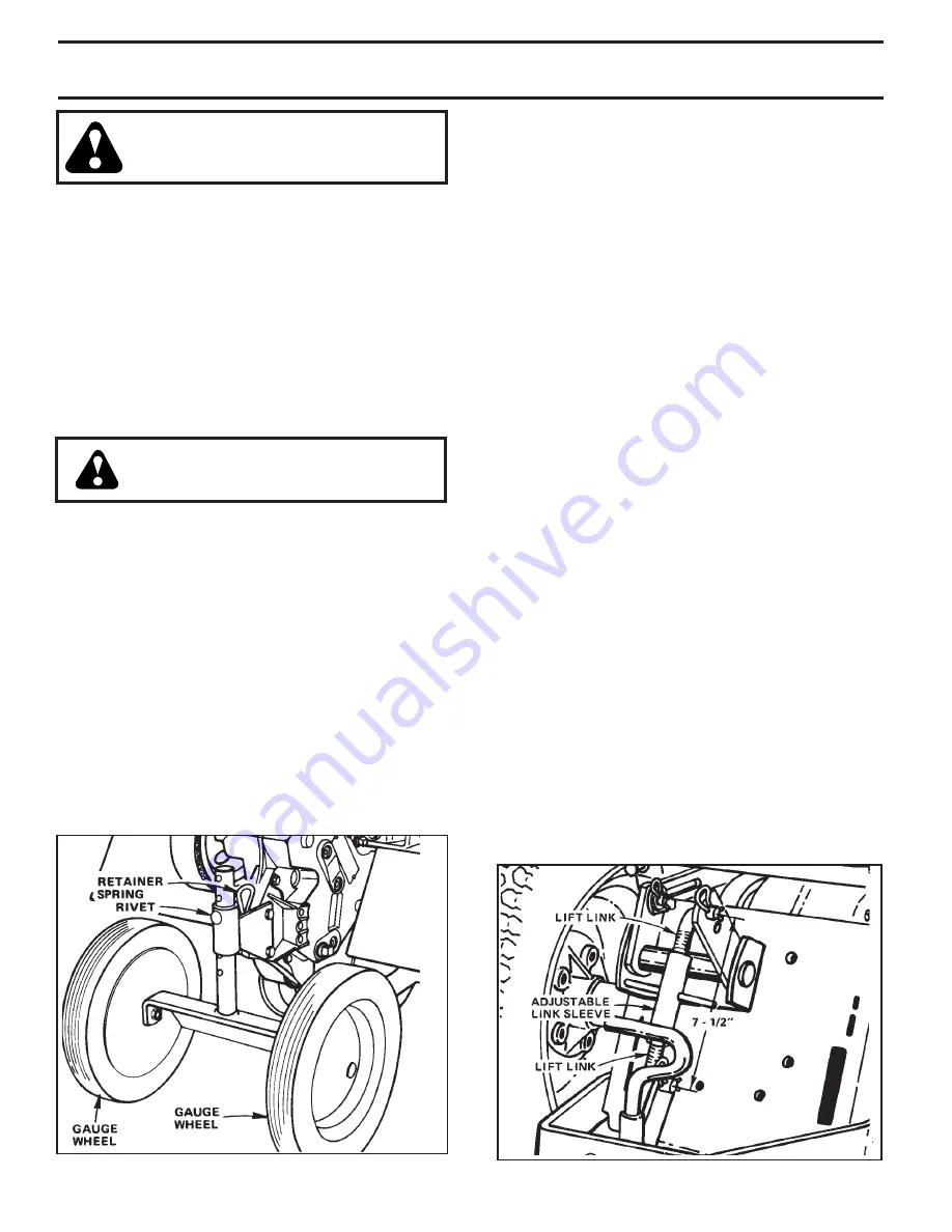
Set gauge wheels so that tiller will penetrate soil to a
depth of 2 to 3 inches. Place rivet in the second or third
hole from the bottom to attain this depth. The tiller engine
should be run at full throttle except when cultivating small
plants, a slower engine speed is necessary to prevent
burying the plants.
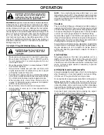
OPERATION DO’S AND DON’TS
Always dis en gage tine clutch lever (Fig. 3) and stop engine
when traveling to or from fi eld (garden) or when not tilling.
Lift tiller out of the ground when turning corners.
Do not put tractor in reverse gear while tiller is in the ground.
Before leaving tractor seat, stop tractor, shift tractor to
“NEUTRAL” position, throttle down and stop tractor en gine,
set parking brake, remove ignition key and then dis en gage
tine clutch lever, throttle down and stop tiller engine, lower
tiller to ground. Disconnect spark plug.
Disconnect spark plug wires before making any ad just -
ments, repairs or to remove debris in tines.
CAUTION: Fill to bottom of gas tank
fi ller neck. Do not overfi ll. Wipe off any
spilled oil or fuel. Do not store, spill or
use gas o line near an open fl ame.
WARNING:
Experience indicates that alcohol blended fuels
called gasohol or using ethanol or methanol) can attract
moisture which leads to separation and formation of acids
during storage. Acidic gas can damage the fuel system
of an engine while in storage. To avoid engine problems,
the fuel system should be emptied before storage of 30
days or longer. Drain the gas tank, start the engine and
let it run until the fuel lines and carburetor are empty.
Use fresh fuel next season. See Storage sections of this
manual for additional information. Never use engine or
carburetor cleaner products in the fuel tank or permanent
damage may occur.
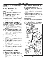
TO START TILLER ENGINE (See Fig. 3)
CAUTION: Keep the tine clutch lever in
“DIS EN GAGED” position when start-
ing engine.
• Make sure spark plug wire is connected to spark plug.
• Move choke control lever to “FULL CHOKE” position
for cold engine start. For warm engine start do not
use choke control.
• Move tiller engine throttle to midway between “FAST”
and “SLOW” positions.
• Grasp starter handle and pull rope out slowly until
engine reaches start of compression cycle (rope will
pull slightly harder at this point).
• Pull rope with a rapid, continuous, full arm stroke. Keep
a fi rm grip on starter handle and let rope rewind slowly.
Do not let starter handle snap back against starter.
• When engine starts, slowly move choke control on
en gine “1/2 CHOKE” position and then to “NO CHOKE”
position as engine warms up.
• Move throttle control to desired running position.
• Allow engine to warm up for a few minutes before
engaging tines.
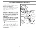
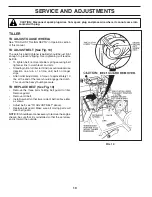
FIG. 4
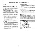
FIG. 5


