
7
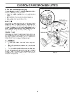
CUSTOMER RESPONSIBILITIES
GENERAL RECOMMENDATIONS
The warranty on this attachment does not cover items that
have been subjected to operator abuse or negligence. To
receive full value from the warranty, operator must main tain
unit as instructed in this manual.
Some adjustments will need to be made periodically to
properly maintain your unit.
All adjustments in the Service and Adjustments section
of this manual should be checked at least once each
season.
• Once a year you should replace the spark plug, clean
or replace air fi lter, and check tines and belts for wear.
A new spark plug and clean air fi lter assure proper
air-fuel mixture and help your engine run better and
last longer.
BEFORE EACH USE
• Check engine oil level.
• Check brake operation.
• Check tire pressure.
• Check for loose fasteners.
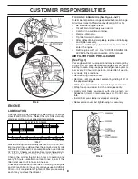
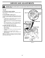
TILLER
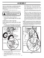
TRANSMISSION LUBRICATION (See Fig. 6)
Check transmission oil level after fi rst fi ve (5) hours of
operation and every ten (10) hours thereafter.
• Check transmission oil with the tiller leveled on level
ground.
• Remove oil fi ll plug. Oil should be level with the bot-
tom of fi ller plug hole. If necessary add SAE 30 motor
oil or equivalent. SAE 5W-30 motor oil may be used
in areas where temperature is consistently 32°F or
lower.
• Tighten oil fi ll plug securely each time you check the
oil level.
NOTE:
It is not necessary to change the oil in tiller trans-
mis sion. If for any rea son, it must be changed, ca pac i ty
is 1-1/4 quarts.
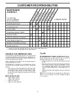
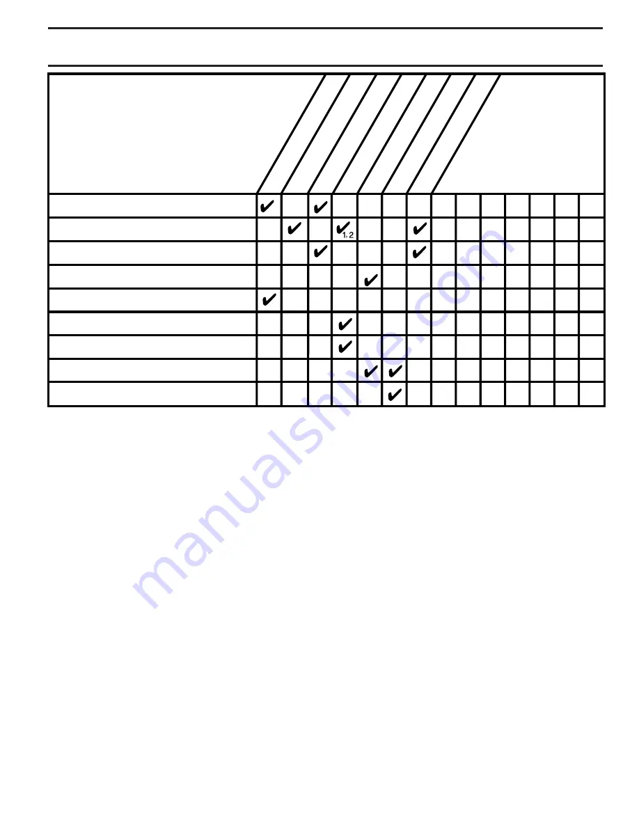
MAINTENANCE
SCHEDULE
FILL IN DATES
AS YOU COMPLETE
REGULAR SERVICE
Check Engine Oil Level
Change Engine Oil
Oil Pivot Points
Inspect Air Screen
Inspect Spark Arrester / Muffler
Clean Air Filter/Foam Pre-Cleaner
Clean Engine Cylinder Fins
Replace Air Filter/Paper Cartridge
BEFORE EACH USE
EVERY 25 HOURS
EVERY 5 HOURS EVERY 50 HOURS
SERVICE DATES
2
1 - Change more often when operating under a heavy load or in high ambient temperatures.
2 - Service more often when operating in dirty or dusty conditions.
FIRST 2 HOURS
EVERY 100 HOURS
BEFORE STORAGE
Replace Spark Plug


