34
Lower and Upper Case Ass’y (continued)
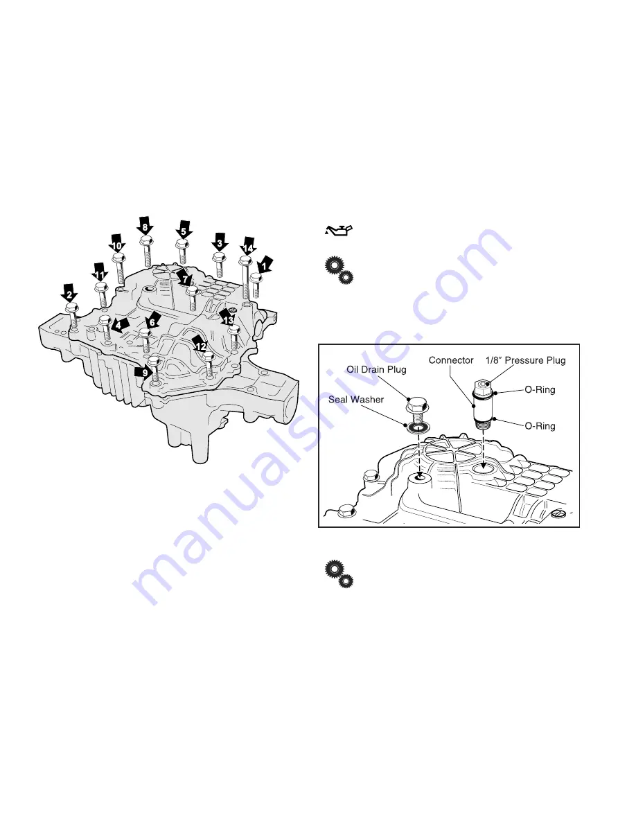
4. Install (1) M8x75 Bolt (
arrow 14
), (2) M8x40 Bolts (
ar-
rows 8 & 10
) and (11) M8x30 Bolts (
arrows 1–13
) to
Lower Case/Upper Case.
(Fig. 46)
5. Torque Bolts (12 mm wrench) utilizing the tightening
sequence diagram.
(Fig. 46)
Tightening torque:
2.3 ~ 2.5 kg-m
22.6 ~ 24.6 N-m
17 ~ 18 ft lbs.
Fig. 46, Torque Sequence for Upper & Lower Case
6. Install Oil Drain Plug (12 mm wrench) with new Seal
Washer into Lower Case.
Tightening torque:
1.3 ~ 1.7 kg-m
12.8 ~ 16.7 N-m
113 ~ 148 in. lbs.
7. Install (2) new O-rings and the 1/8” plug (5 mm hex
wrench) onto Connector (Pressure Fill Plug).
Apply grease to surface of O-rings.
If 1/8 inch Pressure Plug was removed ap-
ply Teflon tape to threads of plug before reinstalling.
(Fig. 47)
8. Install Connector through Lower Case’s opening into
Center Case port.
Fig. 47, Oil Plug & Connector Install
Before installing the Connector, fill transmission
rotor groups with new oil through the connector port
of Center Case while hand rotating Motor Shaft using
Brake Drum for gripping assistance. This procedure is
effective for quick air bleeding.


