18
Before Starting Assembly
Before starting the assembly of the Transaxle check all parts
to ensure that they are clean and free of any foreign
debris, this includes your work area and tools.
Have on hand a new Seal Kit (19215499150). Check contents
of kit for possible defects before installation. Note that
the kit is designed to cover all K61 models. You may or
may not use all the items, in the kit, on your particular
model. The Seal Kit, as well as other parts necessary for
replacement, can be ordered on-line by visiting Tuff
Torq’s Web Site at: www.tufftorq.com (See “Ordering
Replacement Parts”, page ii).
Bypass Shaft Assembly
1. Place the Upper Case on a service stand in the service
position (flange side up).
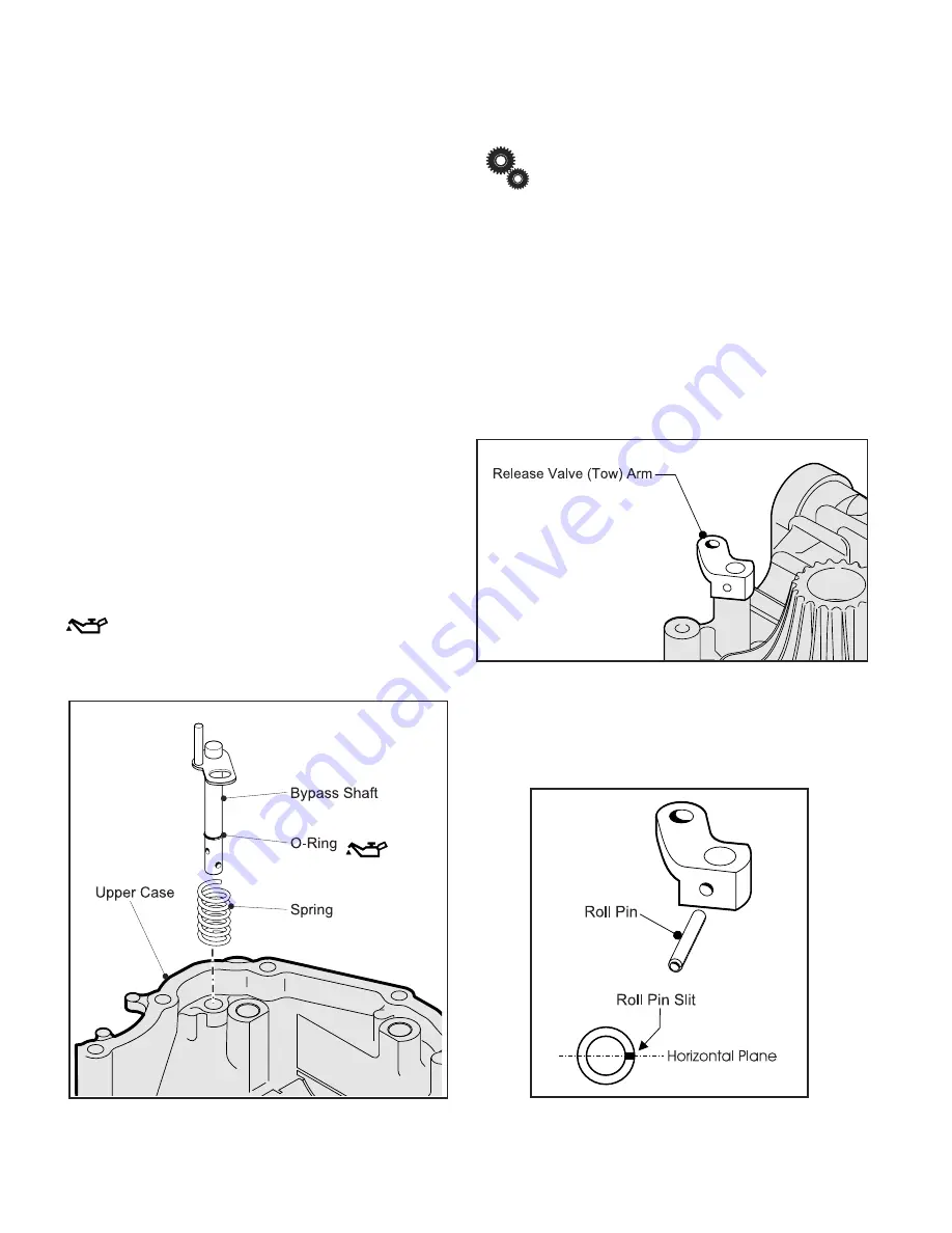
2. Install a new O-ring onto the Bypass Shaft.
3. Install the Spring onto the Bypass Shaft.
4. Install the Spring and Bypass Shaft into the hole on the
Upper Case.
(Fig. 1)
Apply a light coating of grease to the surface of
the O-ring. Also, apply a small amount of grease into
mating hole of Upper Case.
Fig. 1, Bypass Shaft Assembly
Rather than lubricating packing items (O-rings
and Seals) in advance, apply a light coating of grease
just prior to their installation. This will minimize the pos-
sibility of debris collecting of packing items while wait-
ing to be installed.
5. Since the Bypass Shaft is spring loaded it is recom-
mended that the Release Valve (Tow) Arm be connected
before proceeding.
◆
From the reverse side of the Upper Case, mount the
Release Valve Arm onto the Bypass Shaft; then, align
and secure with Roll Pin.
(Fig. 2)
Fig. 2, Release Valve Arm Assembly
◆
Always install Roll Pins with the slit on a horizontal
plane. This will enable the pin greater holding ability.
Fig. 2a, Roll Pin Installation
Assembly of Transaxle


