IGSF-ASC-L / ASCS-L-0308
8
General
•
Display: the display can show time-of-day, zone
temperature, evaporator temperature and it can
also cycle between zone temperature and time-of-
day
•
Temperature format: the control can use
temperatures in °F or °C
•
Fan enable during defrost: to control the fan
operation during defrost (on or off)
•
Minimum compressor off time: for short cycle
protection, between 0 and 15 min
•
Minimum compressor on time: between 0 and 15
min
•
Alarm delay: a time delay can be configured for the
alarm to operate (between 0 and 59 min)
DEFROST
•
Defrost type: it can programmed for hot gas or
electric heater defrost. An off cycle defrost type
can be configured by selecting the electric defrost
option and not connecting any device to the
defrost relay
•
Number of defrosts per day: between 1 and 8.
There is also an option for 1 defrost every 48
hours
•
Defrost cycle: a choice among defrost start time
(real time clock), accumulated compressor run
time or temperature initiation defrost
•
Fan delay: amount of time that the fan will remain
off after defrost is terminated (0 to 15 min)
•
Pump down: amount of time the compressor
remains on after defrost initiates (0 to 59 min)
•
Drip time: amount of time the compressor is
locked out after defrost is terminated (0 to 59 min)
•
Defrost duration time: amount of time for the
defrost duration. It also functions as a back-up for
temperature termination.
•
Defrost termination temperature: temperature
that will cause the defrost to terminate (if reached
before defrost duration time)
•
Fan start temperature: temperature that will cause
the fan to re-start after defrost
SETPOINT
•
Setpoint temperature (cut-out): a setpoint
temperature can be programmed to control the
compressor operation. The range is -40 to 60 °F
•
Cut-in differential: differential between the cut-out
(setpoint) and the cut-in temperature. The range is
1 to 25 °F
•
High and low temperature alarm setpoint: high and
low alarms for the temperature can be set. The
ranges are -40 to 60 °F for each of the alarms (high
and low)
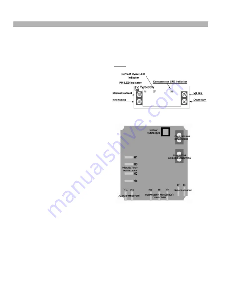
GRAPHIC DESCRIPTION / DIMENSIONS
Display
L
a
y
o
u
t
Fig. 1
Relay Board Layout
Fig. 2
CONTROL WIRING
•
All wiring should conform to the National Electric
Code and local regulations.
•
Use copper conductors only.
•
Electrical leads should not be taut; allow slack for
temperature change and vibration.
Paragon ERC 2 Electronic Controller for Self Contained Cases Cont’d


