2 of 10
HUSSMANN CORPORATION, Bridgeton, MO 63044-2483 U.S.A.
C2X-XEP
Technical Data Sheet
Engineering
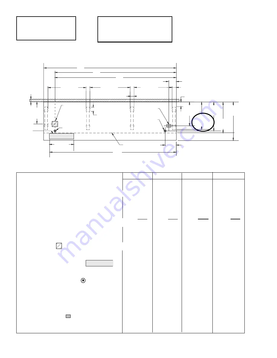
Plan Views
Dimensions shown as inches and (mm).
Dairy/Delicatessen
Precut & Packaged Produce
01-2005
NOTE: Case-to-Case Electrical Connections
are made IN FRONT OF SPLASHGUARD.
4
3
/
4
(120)
Splashguard
31
5
/
8
(804)
42
(1064)
A
41
1
/
2
(1054)
3 In.
(77 mm)
Required
Air Gap
Refrigeration
Outlet
Electrical
Stub Up Area
6 x 6
(152x152)
Waste Outlet
Waste Outlet
FRONT
26
1
/
4
(665)
B
D
8
(203)
4
1
/
2
(115)
12
1
/
8
(307)
41
1
/
2
(1054)
43
7
/
8
(1114)
C
Wireway
4
3
/
4
(120)
26
1
/
2
(673)
4
1
/
4
(108)
24
(612)
33
1
/
2
(851)
Electrical
Field
Connection
30
1
/
4
(768)
C2X
4 ft
6 ft
8 ft
12 ft
General
(A)
Case Length
(without ends or partitions)
48
3
/
8
(1229)
72
3
/
8
(1838)
96
3
/
8
(2448)
144
1
/
2
(3670)
(Each end and insulated partition adds 1
1
/
2
in. (38 mm) to case line up.)
Maximum O/S dimension of case back to front
(includes bumper)
42 (1064)
42 (1064)
42 (1064)
42 (1064)
Back of case to front of splashguard
33
1
/
2
(851)
33
1
/
2
(851)
33
1
/
2
(851)
33
1
/
2
(851)
Back of case to O/S edge of front leg
30
1
/
4
(768)
30
1
/
4
(768)
30
1
/
4
(768)
30
1
/
4
(768)
Distance between edges of external legs and center legs
NA
29
1
/
2
(750)
41
1
/
2
(1054)
41
1
/
2
(1054)
Distance between edges of center legs
NA
NA
NA
43
7
/
8
(1114)
Distance between front legs and splashguard
2
3
/
4
(70)
2
3
/
4
(70)
2
3
/
4
(70)
2
3
/
4
(70)
Electrical Service
(Electrical Field Wiring connection point)
(B)
RH End of case to center of stub up area
36
1
/
4
(921)
60
1
/
4
(1530)
84
1
/
4
(2140)
132
3
/
8
(3363)
Back of case to center of stub up area
24 (612)
24 (612)
24 (612)
24 (612)
Length of electrical wireway
26
1
/
2
(673)
26
1
/
2
(673)
26
1
/
2
(673)
26
1
/
2
(673)
(C)
RH End of case to LH end of wireway
42
1
/
8
(1070)
66
1
/
8
(1680)
90
1
/
8
(2289)
138
1
/
4
(3511)
Waste Outlets
(One each end)
(D)
RH End of case to the center of LH waste outlet
36
1
/
4
(921)
60
1
/
4
(1530)
84
1
/
4
(2140)
132
3
/
8
(3363)
RH End of case to the center of RH waste outlet
12
1
/
8
(307)
12
1
/
8
(307)
12
1
/
8
(307)
12
1
/
8
(307)
Back O/S of case to center of waste outlets
31
5
/
8
(804)
31
5
/
8
(804)
31
5
/
8
(804)
31
5
/
8
(804)
Schedule 40 PVC drip pipe
1
1
/
4
(32)
1
1
/
4
(32)
1
1
/
4
(32)
1
1
/
4
(32)
Refrigeration Outlet
Back of case to center of refrigeration outlet
26
1
/
4
(665)
26
1
/
4
(665)
26
1
/
4
(665)
26
1
/
4
(665)
RH end of case to center of refrigeration outlet
8 (203)
8 (203)
8 (203)
8 (203)
PHYSICAL DATA
Merchandiser Drip Pipe (in.)
1
1
/
4
Merchandiser Liquid Line (in.)
3
/
8
Merchandiser Suction Line (in.)
7
/
8
Wireway


