Rev. 0508
7
Electrical Service Receptacles (When Applicable)
The receptacles located on the exterior of the merchandiser
are intended for scales and lighted displays. They are not
intended nor suitable for large motors or other external
appliances.
BEFORE SERVICING
ALWAYS DISCONNECT ELECTRICAL
POWER AT THE MAIN DISCONNECT
WHEN SERVICING OR REPLACING ANY
ELECTRICAL COMPONENT.
This includes (but not limited to) Fans, Heaters
Thermostats, and Lights.
Field Wiring and Serial plate Amperage
Field Wiring must be sized for component amperes printed
on the serial plate. Actual ampere draw may be less than
specified. Field wiring from the refrigeration control panel to
the merchandisers is required for refrigeration thermostats.
Most component amperes are listed in the “Case Specs”
section, but always check the serial plate.
Ballast Location
Ballasts are located within the access panel that runs the
length of the rear of the case. Refer to diagram on page 6.
Electrical
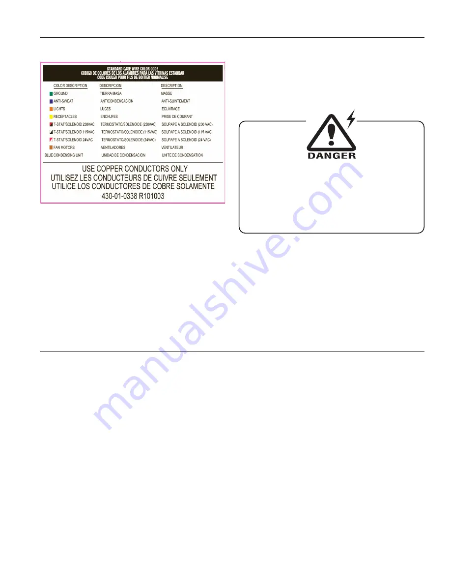
Wiring Color Code
CASE MUST BE GROUNDED
NOTE: Refer to label illustrated above that is affixed to case
to determine the actual configuration as checked in the
“TYpE INSTALLED” boxes.
Electrical Circuit Identification
Standard lighting for all models will be full length fluorescent
lamps located within the case at the top.
The switch controlling the lights, the plug provided for
digital scale, and the thermometer are located at the rear
of the case mullion.
The receptacle that is provided on the exterior back of these
models is intended for computerized scales with a five amp
maximum load, not for large motors or other high wattage
appliances. It should be wired to a dedicated circuit.
Finishing Touches
plexiglass Joining Instructions
Note:
All cases in a line up are set, leveled and joined together
in the factory to ensure proper alignment and tight joints
between the cases. To obtain equally tight joints between
cases, it is critical to use the GE 1200 silicone (supplied
with cases) for sealing case joints. Only the use of
silicone allows case joints to pull up tight! DO NOT USE
pERMAGUM! Use of permagum will cause large gaps at
case joints.
parts List
• 1” Plastic rod 3/16” diameter
• Acrylic Solvent Cement (IPS weldon #40 or
comparable)
• Masking tape and duct tape (not supplied)
Instructions
1. Prepare front plexiglass for cement application by
placing masking tape, a maximum 1/16 of an inch
from the seam, on both sides front and back. Tape is
to protect plexiglass from cement spill over. Scarring
will occur if cement touches clear plexiglass.
. Separate front plexiglass pieces enough to apply a
bead of #40 cement down one edge inside of seam
and plastic rod area.
3. Realign front plexiglass and push together tightly.
Insert the plastic rod until flush with top of plexiglass.
4. Apply tape (” duct tape recommended) across
face of seam to secure plexiglass from shifting while
cement dries (approximately 1 hour).
5. With a little silicone, attach the plex clip over the joint
in the glass.
Weldon #40 (2-part) Cement - Mixing Instructions
1. Bring Parts “A” and “B” to room temperature before
mixing.
. Add Part “A” to Part “B”. They have been
premeasured at the factory.
3. Stir slowly and evenly, as to avoid air bubbles. Mix for
1-3 minutes.


