background image

IGUP-RGD-0106

34

APPENDIX A. – Temperature Guidlines

The refrigerators should be operated according to the manufacturer’s
published engineering specifications for entering air temperatures for
specific equipment applications. Table 1 shows the typical temperature
of the air entering the food zone one hour before the start of defrost
and one hour after defrost for various categories of refrigerators.
Refer to Appendix C for Field Evaluation Guidelines.

TABLE 1

Type of Refrigerator

Typical Entering

 Air Temperature

I. OPEN DISPLAY

A. Non frozen:

1) Meat

28

°

F

2) Dairy/Deli

32

°

F

3) Produce

a. Processed

36

°

F

b. Unprocessed

45

°

F

B. Frozen

0

°

F

C. Ice Cream

-5

°

F

II. CLOSED DISPLAY

A. Non frozen:

1) Meat

34

°

F

2) Dairy/Deli

34

°

F

3) Produce

a. Processed

36

°

F

b. Unprocessed

45

°

F

B. Frozen

0

°

F

C. Ice Cream

-5

°

F

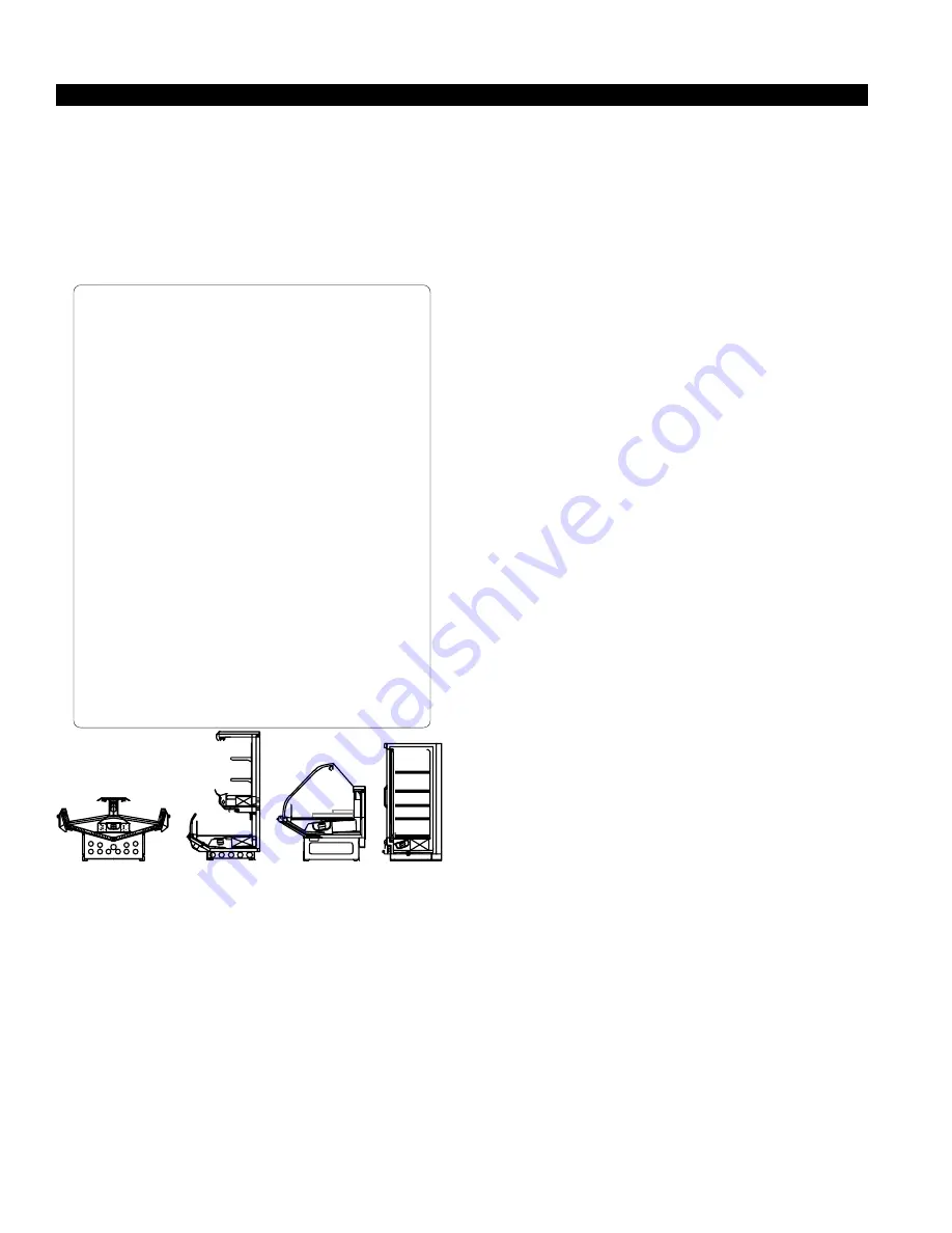
Single Deck

Multi Deck

ServiceCase

Reach-In

I. Open Display Styles

II. Closed Display Styles

APPENDIX B. – Application Recommendations

1.0 Temperature performance is critical for controlling bacteria

growth. Therefore, the following recommendations are included in
the standard. They are based on confirmed field experience over
many years.

1.1 The installer is responsible for following the installation instruc-

tions and recommendations provided by the manufacturer for the
installation of each individual type refrigerator.

1.2 Refrigeration piping should be sized according to the equipment

manufacturer’s recommendations and installed in accordance with
normal refrigeration practices. Refrigeration piping should be

insulated according to the manufacturer’s recommendations.

1.3 A clogged waste outlet blocks refrigeration. The installer is

responsible for the proper installation of the system which
dispenses condensate waste through an air gap into the building
indirect waste system.

1.4 The installer should perform a complete start-up evaluation prior to

the loading of food into the refrigerator, which includes such items as:
a) Initial temperature performance, Coils should be properly fed with

a refrigerant according to manufacturer’s recommendations.

b) Observation of outside influences such as drafts, radiant

heating from the ceiling and from lamps. Such influence should
be properly corrected or compensated for.

c) At the same time, checks should be made of the store dry-

bulb and wet-bulb temperatures to ascertain that they are
within the limits prescribed by the manufacturer.

d) Complete start-up procedures should include checking through

a defrost to make certain of its adequate frequency and length
without substantially exceeding the actual needs. This should
include checking the electrical or refrigerant circuits to make
sure that defrosts are correctly programmed for all the
refrigerators connected to each refrigeration system.

e) Recording instruments should be used to check performance.

APPENDIX C. – Field Recommendations

Recommendations for field evaluating the performance of retail
food refrigerators

1.0 The most consistent indicator of display refrigerator performance

is temperature of the air entering the product zone (see
Appendix A). In practical use, the precise determination of return
air temperature is extremely difficult. Readings of return air
temperatures will be variable and results will be inconsistent. The
product temperature alone is not an indicator of refrigerator
performance.

NOTE

: Public Health will use the temperature of the product in

determining if the refrigerator will be allowed to display potentially
hazardous food. For the purpose of this evaluation, product
temperature above the FDA Food Code 1993 temperature for
potentially hazardous food will be the first indication that an
evaluation should be performed. It is expected that all refrigerators
will keep food at the FDA Food Code 1993 temperature for potentially
hazardous food.

1.1 The following recommendations are made for the purpose of

arriving at easily taken and understood data which, coupled with
other observations, may be used to determined whether a display
refrigerator is working as intended:
a) INSTRUMENT – A stainless steel stem-type thermometer is

recommended and it should have a dial a minimum of 1 inch
internal diameter. A test thermometer scaled only in Celsius or
dually scaled in Celsius and Fahrenheit shall be accurate to
1

°

C (1.8

°

F). Temperature measuring devices that are scaled

Appendices

Summary of Contents for Chino RGD

Page 1: ... Chino RGD Upright Deli Case Rev 0106 Installation Operation Manual RGD Upright Deli Case p n IGUP RGD 0106 INSTALLATION OPERATION GUIDE ...

Page 2: ...rms SHORTAGES Check your shipment for any possible shortages of mate rial If a shortage should exist and is found to be the re sponsibility of Hussmann Chino notify Hussmann Chino If such a shortage involves the carrier notify the carrier imme diately and request an inspection Hussmann Chino will acknowledge shortages within ten days from receipt of equipment HUSSMANN CHINO PRODUCT CONTROL The ser...

Page 3: ...ectrical Bottom Refrigeration RGD Scale 1 2 1 1 50 Variable Lengths 24 RGD72 24 Refrigerated Gondola Display 72 High 24 Wide Display Area 72 8 24 7 3 4 51 1 4 5 Lighted Shelf Optional Shelves Condiment Shelf 12 RGD72 24 SC Self Contained Refrigerated Gondola Display 72 High 24 Wide Display Area Compressor 1 0 13 1 2 12 6 12 72 8 24 7 3 4 51 1 4 5 24 85 1 2 4 8 89 6 12 Optional Shelves RGD83 24 Ref...

Page 4: ...igerated Gondola Insert Display 72 High 30 Wide 30 72 49 1 4 8 3 4 8 5 3 4 19 1 2 18 30 1 4 84 1 8 60 5 8 17 5 8 19 3 8 18 RGD8330 Ref Gondola Display Scale 1 2 ELEC DROP ELEC DROP REF DROP DRAIN 1 30 1 2 72 RGD83 30 Plan View of 6 case Scale 1 2 ...

Page 5: ... proper operation water drainage glass align ment and operation of the hinges supporting the glass Leveling the case correctly will solve most hinge operation problems NOTE A To avoid removing concrete flooring begin lineup leveling from the highest point of the store floor B When wedges are involved in a lineup set them first All cases were leveled and joined prior to shipment to insure the close...

Page 6: ...r discharge and be tween the front legs Do not use cam locks to pull cases together ENDS Bolt the end s onto the case using the bolts provided in the pre drilled holes on the side s of the case DO NOT SEAL JOINT TRIM TO FLOOR Installation cont 4 Avoid long runs of condensate drains Long runs make it impossible to provide the fall necessary for good drainage 5 Provide a suitable air break between t...

Page 7: ...cess panel s ELECTRONIC EXPANSION VALVE OPTIONAL A wide variety of electronic expansion valves and case controllers can be utilized Please refer to EEV and con troller manufacturers information sheet Sensors for elec tronic expansion valves will be installed on the coil inlet coil outlet and in the discharge air Some supermarkets require a 4th sensor in the return air Case controllers will be loca...

Page 8: ...d wiring from the refrigeration control panel to the merchandisers is required for re frigeration thermostats Most component amperes are listed in the Case Specs section but always check the serial plate BALLAST LOCATION Ballasts are located within the access panel that runs the length of the rear of the case Refer to diagram on page 6 T STAT LOCATION RGD SC RGD TheT stats are laocted within the e...

Page 9: ... being installed next to each other the factory fitted continuous fascia may need to be in stalled All fasciae rest on the top of their cases The self contained fascia has a hook that needs to be slid through a gusset on the side of the case ...

Page 10: ...34 28 300 28 Forced 8 x 30 1 20 4 1 90 3 86 5 Air 6 1 600 9 600 20 34 28 300 28 Forced 8 x 30 2 20 4 3 80 3 86 5 Air 8 1 600 12 800 20 34 28 300 28 Forced 8 x 30 2 20 4 3 80 6 56 5 Air 12 1 600 19 200 20 34 28 300 28 Forced 8 x 30 3 20 4 5 70 9 26 5 Air RGD 30 Extra Deep 83 Tall 4 1 800 7 200 20 34 28 300 28 Forced 8 x 30 1 20 4 1 90 3 86 5 Air 6 1 800 10 800 20 34 28 300 28 Forced 8 x 30 2 20 4 3...

Page 11: ... NEWWIRE RGD 72 CASES W2300005 4 CASE REMOTE WIRING DIAGRAM LIGHT SWITCH 125 01 0307 BUNDLE COLOR ORANGE BALLAST 125 01 3266 FULHAM LH3 120 L BALLAST 125 01 0681 MAGNETEK B260I120HP BUNDLE COLOR BROWN CANOPY LIGHT 1 F48T12 830 SHELF LIGHTING 4 FP28T5 830 EVAPORATOR FAN GE 9W 115V L N POWER 115 VAC 50 60 Hz 3 WIRE L N M CAP UNUSED BLUE LEAD BALLAST 125 01 3266 FULHAM LH3 120 L BUNDLE COLOR BLACK WH...

Page 12: ...TE WIRING DIAGRAM LIGHT SWITCH 125 01 0307 BUNDLE COLOR ORANGE BALLAST 125 01 0681 MAGNETEK B260I120HP BUNDLE COLOR BROWN CANOPY LIGHTS 2 F36T12 830 EVAPORATOR FANS 2 GE 9W 115V L N POWER 115 VAC 50 60 Hz 3 WIRE L N M M BALLAST 125 01 3266 FULHAM LH3 120 L BALLAST 125 01 3266 FULHAM LH3 120 L BALLAST 125 01 3266 FULHAM LH3 120 L SHELF LIGHTING 8 FP21T5 830 2ND ROW 3RD ROW 1ST ROW BALLAST 125 01 32...

Page 13: ... WIRING DIAGRAM LIGHT SWITCH 125 01 0307 BUNDLE COLOR ORANGE BALLAST 125 01 3266 FULHAM LH3 120 L BALLAST 125 01 3266 FULHAM LH3 120 L BALLAST 125 01 3266 FULHAM LH3 120 L BALLAST 125 01 0681 MAGNETEK B260I120HP CANOPY LIGHTS 2 F48T12 830 SHELF LIGHTING 8 FP28T5 830 2ND ROW 3RD ROW 1ST ROW L N POWER 115 VAC 50 60 Hz 3 WIRE BALLAST 125 01 3266 FULHAM LH3 120 L 4TH ROW BUNDLE COLOR BROWN EVAPORATOR ...

Page 14: ...OR ORANGE BALLAST 125 01 3266 FULHAM LH3 120 L BALLAST 125 01 3266 FULHAM LH3 120 L BALLAST 125 01 3266 FULHAM LH3 120 L BALLAST 125 01 3266 FULHAM LH3 120 L BALLAST 125 01 0681 MAGNETEK B260I120HP BUNDLE COLOR BROWN CANOPY LIGHTS 2 F72T12 830 SHELF LIGHTING 12 FP28T5 830 2ND ROW 3RD ROW 1ST ROW EVAPORATOR FANS 3 GE 9W 115V L N POWER 115 VAC 50 60 Hz 3 WIRE POWER 115 VAC 50 60 Hz 3 WIRE L N M M M ...

Page 15: ...300009 4 CASE REMOTE DIAGRAM LIGHT SWITCH 125 01 0307 BUNDLE COLOR ORANGE BALLAST 125 01 3266 FULHAM LH3 120 L BALLAST 125 01 0681 MAGNETEK B260I120HP BUNDLE COLOR BROWN CANOPY LIGHT 1 F48T12 830 SHELF LIGHTING 5 FP28T5 830 EVAPORATOR FAN GE 9W 115V L N POWER 115 VAC 50 60 Hz 3 WIRE L N M CAP UNUSED BLUE LEAD BALLAST 125 01 3266 FULHAM LH3 120 L CAP UNUSED RED LEAD BALLAST 125 01 3266 FULHAM LH3 1...

Page 16: ... 01 0307 BUNDLE COLOR ORANGE BALLAST 125 01 0681 MAGNETEK B260I120HP BUNDLE COLOR BROWN CANOPY LIGHTS 2 F36T12 830 EVAPORATOR FANS 2 GE 9W 115V L N POWER 115 VAC 50 60 Hz 3 WIRE L N M M BALLAST 125 01 3266 FULHAM LH3 120 L BALLAST 125 01 3266 FULHAM LH3 120 L BALLAST 125 01 3266 FULHAM LH3 120 L SHELF LIGHTING 10 FP21T5 830 2ND ROW 3RD ROW 1ST ROW BALLAST 125 01 3266 FULHAM LH3 120 L BALLAST 125 0...

Page 17: ... 0307 BUNDLE COLOR ORANGE BALLAST 125 01 3266 FULHAM LH3 120 L BALLAST 125 01 3266 FULHAM LH3 120 L BALLAST 125 01 3266 FULHAM LH3 120 L BALLAST 125 01 0681 MAGNETEK B260I120HP CANOPY LIGHTS 2 F48T12 830 SHELF LIGHTING 10 FP28T5 830 2ND ROW 3RD ROW 1ST ROW L N POWER 115 VAC 50 60 Hz 3 WIRE BALLAST 125 01 3266 FULHAM LH3 120 L BALLAST 125 01 3266 FULHAM LH3 120 L 4TH ROW 5TH ROW BUNDLE COLOR BROWN ...

Page 18: ...3266 FULHAM LH3 120 L BALLAST 125 01 3266 FULHAM LH3 120 L BALLAST 125 01 3266 FULHAM LH3 120 L CAP UNUSED RED LEAD BALLAST 125 01 0681 MAGNETEK B260I120HP BUNDLE COLOR BROWN CANOPY LIGHTS 2 F72T12 830 SHELF LIGHTING 15 FP28T5 830 2ND ROW 3RD ROW 1ST ROW EVAPORATOR FANS 3 GE 9W 115V L N POWER 115 VAC 50 60 Hz 3 WIRE POWER 115 VAC 50 60 Hz 3 WIRE L N M M M BALLAST 125 01 3266 FULHAM LH3 120 L BALLA...

Page 19: ...FULHAM LH3 120 L BALLAST 125 01 0681 MAGNETEK B260I120HP BUNDLE COLOR BROWN CANOPY LIGHT 1 F48T12 830 SHELF LIGHTING 4 FP28T5 830 EVAPORATOR FAN GE 9W 115V L N POWER 115 VAC 50 60 Hz 3 WIRE L N M CAP UNUSED BLUE LEAD S C R M C 2 1 3 R S T X 4 N 3 1 2 L1 L2 COMPRESSOR MOTOR CONDENSER FAN 208 VAC START CAPACITOR EXTERNAL PROTECTOR T STAT PRESSURE SAFETY POWER SWITCH DEFROST TIMER PARAGON 8045 20 208...

Page 20: ...EVAPORATOR FANS 2 GE 9W 115V L N POWER 115 VAC 50 60 Hz 3 WIRE L N M S C R M C 2 1 3 R S T X 4 N 3 1 2 L1 L2 N COMPRESSOR MOTOR CONDENSER FAN 208 VAC START CAPACITOR EXTERNAL PROTECTOR T STAT PRESSURE SAFETY POWER SWITCH DEFROST TIMER PARAGON 8045 20 208 V 60 Hz 125 01 0715 5 2 1 POTENCIAL RELAY RED YELLOW B LU E BLACK RUN CAPACITOR POWER 208 230 VAC 60 Hz 4 WIRE CONTACTOR SQUARE D 8910DPA43V02 12...

Page 21: ...NG 8 FP28T5 830 2ND ROW 3RD ROW 1ST ROW L N POWER 115 VAC 50 60 Hz 3 WIRE S C R M C 2 1 3 R S T X 4 N 3 1 2 L1 L2 N COMPRESSOR MOTOR CONDENSER FAN 208 VAC START CAPACITOR EXTERNAL PROTECTOR T STAT PRESSURE SAFETY POWER SWITCH DEFROST TIMER PARAGON 8045 20 208 V 60 Hz 125 01 0715 5 2 1 POTENCIAL RELAY RED YELLOW B L U E BLACK RUN CAPACITOR POWER 208 230 VAC 60 Hz 4 WIRE S C R C 2 1 3 R S COMPRESSOR...

Page 22: ...OW EVAPORATOR FANS 3 GE 9W 115V L N POWER 115 VAC 50 60 Hz 3 WIRE POWER 115 VAC 50 60 Hz 3 WIRE L N S C R M C 2 1 3 R S T X 4 N 3 1 2 COMPRESSOR MOTOR CONDENSER FAN 208 VAC START CAPACITOR EXTERNAL PROTECTOR T STAT PRESSURE SAFETY POWER SWITCH DEFROST TIMER PARAGON 8045 20 208 V 60 Hz 125 01 0715 5 2 1 POTENCIAL RELAY RED YELLOW B L U E BLACK RUN CAPACITOR POWER 208 230 VAC 60 Hz 4 WIRE CONTACTOR ...

Page 23: ... 01 0681 MAGNETEK B260I120HP BUNDLE COLOR BROWN CANOPY LIGHT 1 F48T12 830 SHELF LIGHTING 5 FP28T5 830 EVAPORATOR FAN GE 9W 115V L N POWER 115 VAC 50 60 Hz 3 WIRE L N M CAP UNUSED BLUE LEAD BALLAST 125 01 3266 FULHAM LH3 120 L CAP UNUSED RED LEAD S C R M C 2 1 3 R S T X 4 N 3 1 2 L1 L2 COMPRESSOR MOTOR CONDENSER FAN 208 VAC START CAPACITOR EXTERNAL PROTECTOR T STAT PRESSURE SAFETY POWER SWITCH DEFR...

Page 24: ... 115V L N POWER 115 VAC 50 60 Hz 3 WIRE L N M S C R M C 2 1 3 R S T X 4 N 3 1 2 L1 L2 N COMPRESSOR MOTOR CONDENSER FAN 208 VAC START CAPACITOR EXTERNAL PROTECTOR T STAT PRESSURE SAFETY POWER SWITCH DEFROST TIMER PARAGON 8045 20 208 V 60 Hz 125 01 0715 5 2 1 POTENCIAL RELAY RED YELLOW B LU E BLACK RUN CAPACITOR POWER 208 230 VAC 60 Hz 4 WIRE CONTACTOR SQUARE D 8910DPA43V02 125 01 0002 1 HP CONDENSI...

Page 25: ...W 3RD ROW 1ST ROW L N POWER 115 VAC 50 60 Hz 3 WIRE S C R M C 2 1 3 R S T X 4 N 3 1 2 L1 L2 N COMPRESSOR MOTOR CONDENSER FAN 208 VAC START CAPACITOR EXTERNAL PROTECTOR T STAT PRESSURE SAFETY POWER SWITCH DEFROST TIMER PARAGON 8045 20 208 V 60 Hz 125 01 0715 5 2 1 POTENCIAL RELAY RED YELLOW B L U E BLACK RUN CAPACITOR POWER 208 230 VAC 60 Hz 4 WIRE S C R C 2 1 3 R S COMPRESSOR MOTOR START CAPACITOR...

Page 26: ... L N POWER 115 VAC 50 60 Hz 3 WIRE POWER 115 VAC 50 60 Hz 3 WIRE L N S C R M C 2 1 3 R S T X 4 N 3 1 2 COMPRESSOR MOTOR CONDENSER FAN 208 VAC START CAPACITOR EXTERNAL PROTECTOR T STAT PRESSURE SAFETY POWER SWITCH DEFROST TIMER PARAGON 8045 20 208 V 60 Hz 125 01 0715 5 2 1 POTENCIAL RELAY RED YELLOW B L U E BLACK RUN CAPACITOR POWER 208 230 VAC 60 Hz 4 WIRE CONTACTOR SQUARE D 8910DPA43V02 125 01 00...

Page 27: ...Rev 0106 27 ...

Page 28: ...IGUP RGD 0106 28 ...

Page 29: ...Rev 0106 29 ...

Page 30: ...IGUP RGD 0106 30 ...

Page 31: ...ct 9 In the Deli Meat and Fish cases completely cover the product each night with a clean damp cloth or butcher paper never use plastic as it does not allow for proper circulation Make sure the cloth or paper is in direct contact with the product 10 Turn and rotate the meat fairly often The blood which gives the pink color works its way downward with time 11 Cold coils remove heat and moisture fro...

Page 32: ...XTERIOR ONLY DO NOT USE ABRASIVES OR STEEL WOOL SCOURING PADS these will mar the finish PLEXIGLASS ACRYLIC CARE CLEANING Clean with plenty of nonabrasive soap or detergent and luke warm water using the bare hand to feel and dislodge any caked on dirt A soft grit free cloth sponge or cham ois may be used but only as a means of carrying the water to the plastic Dry with a clean damp chamois or clean...

Page 33: ...ans or blades need servicing always replace fan blades with the raised embossed side of the blade TOWARD THE MOTOR COPPER COILS The copper coils used in Hussmann merchandisers may be repaired in the field Materials are available from local refrigeration wholesalers Hussmann recommends using 15 Sil Fos for repairs TIPS TROUBLESHOOTING Before calling for service check the following 1 Check electrica...

Page 34: ...ation of outside influences such as drafts radiant heating from the ceiling and from lamps Such influence should be properly corrected or compensated for c At the same time checks should be made of the store dry bulb and wet bulb temperatures to ascertain that they are within the limits prescribed by the manufacturer d Complete start up procedures should include checking through a defrost to make ...

Page 35: ...rigerant and lubricant Does the system use the recommended compressor APPENDIX D Recommendations to user 1 0 The manufacturer should provide instructions and recommendations for proper periodic cleaning The user will be responsible for such cleaning including the cleaning of low temperature equipment within the compartment and the cooling coil area s Cleaning practices particularly with respect to...

Page 36: ...o a period not to exceed five years from date of factory shipment On Hussmann refrigeration systems an additional 4 year extended warranty for the motor compressor assembly is available but must be purchased prior to shipment to be in effect Hussmann reserves the right to inspect the job site installation and reason for failure The motor compressor warranties listed above do not include replacemen...

Page 37: ...ular unit They can be found on a small metal plate on the unit Please note them below for future reference MODEL SERIAL NUMBER Chino Additional copies of thispublication may be obtained by contacting Hussmann Chino 13770 Ramona Avenue Chino California 91710 909 628 8942 FAX 909 590 4910 800 395 9229 Service Record Last service date By ...

Reviews: