background image

Medium Temperature

P/N 428668A

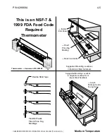
4-3

HUSSMANN CORPORATION • BRIDGETON, MO 63044-2483 (Printed in U.S.A.)

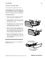
PROCEDURE FOR INSTALLING LIGHTED

SHELVES WITH SINGLE-PRONG
CONNECTOR

Shelf lighting uses parallel
wiring. Please follow these
instructions to ensure good
contact between male and
female connectors.

1. SHUT OFF POWER TO CASE. REMOVE

ALL SHELVES. 

2. Engage each power socket cap and ensure

that each cap is fully seated before cleaning.
Ensure the proper seating of the cap at all
times when the plug is not engaged.

3. Clean the merchandiser as described in the

Care and Cleaning paragraphs of Section 5 –
Maintenance
Keep liquid out of sockets.

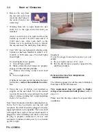
4. Verify that power is at the case and turned on.

Verify that the case light switch is turned
“OFF.” Switch is located in the canopy, on the
left, behind first row of lamps.

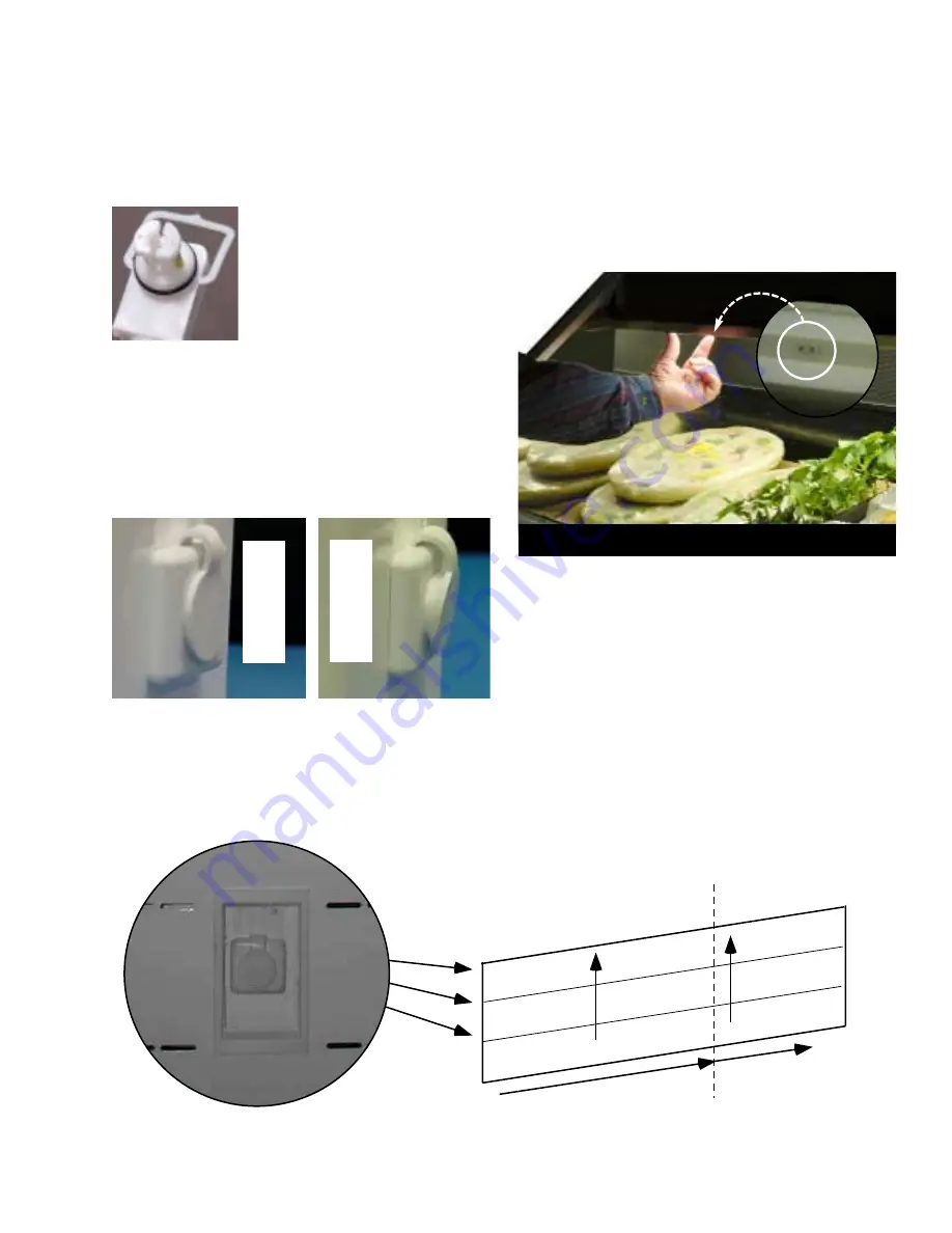
5. See the illustration below. It is typical of  D5,

C5, and D6 models. Note that other models
will have fewer rows of shelves. 

Starting from the left-hand bottom section,
choose the location for the first shelf, X-1.

Secure the shelf in the slotted upright. Make
certain that the shelf is level and that ends are
in the same slot on the left and right upright. It
is important that shelf brackets be properly
seated in the slotted upright. 

Socket with Cap Installed

6 Sockets in

8 ft  (2438 mm) Case

9 Sockets in

12 ft (3658 mm) Case

Always work Left to Right, and Bottom to Top

X-1

X-4

X-7

X-2

X-5

X-8

X-3

X-6

X-9

Canopy Light Switch Location

R

I

G
H

T

W

R
O
N
G

Summary of Contents for CW2-BGE

Page 1: ...uce Merchandisers Installation Operation Manual Shipped With Case Data Sheets P N 428668A Impact Series August 2001 I IM M P P O O R R T TA A N N T T K K e ee ep p i in n s st to or re e f fo or r f f...

Page 2: ...cking 4 1 Load Limit Profile 4 2 Shelf Alignment 4 2 Multideck Shelf Configuration 4 2 Installing Lighted Shelves 4 2 Installing FDA NSF Required Thermometer 4 4 MAINTENANCE Care and Cleaning 5 1 Clea...

Page 3: ...This means that from the time the product is received through storage preparation and display the temperature of the product must be controlled to maximize the life of the product The exterior frames...

Page 4: ...se as possible to its permanent location and then remove all packaging Check for damage before discarding packaging Remove all separately packed accessories such as kits and shelves LEVELING Merchandi...

Page 5: ...handiser as shown 2 Apply the 1 2 in 13 mm gasket around the perimeter of case and across the top as shown Be sure to overlap gaskets as shown Check to be sure that there are no gaps between gasket an...

Page 6: ...inside each case Install splashguard brackets before piping case Use two screws per bracket Attach brackets every 4 feet at pre drilled locations Install splashguard brackets on faceted end in locatio...

Page 7: ...one end carefully peel bottom of top rail free of the retainer and set the rail inside the case c Remove bumpers by pulling bumper away from bumper retainers There are no starter bumpers in the CW2 fa...

Page 8: ...ast bumpers and top rail to length Install the last sections Note If part of plastic top rail pops loose remove that section of top rail and re install according to Step 5 Trying to re install only th...

Page 9: ...ing on the same refrigeration system may be run from merchandis er to merchandiser DO NOT RUN REFRIGERANT LINES THROUGH MERCHANDISERS THAT ARE NOT ON THE SAME REFRIGERATION SYSTEM BRANCH as this may r...

Page 10: ...r lines are exposed to ambient conditions SUCTION LINE Pitch in direction of flow May be reduced by one size at one third of case run load and again after the second third Do not reduce below the case...

Page 11: ...disers require defrost cycles for proper operation Refer to the data sheets for appli cation data The Time Clock initiates defrost The evaporator fans continue to circulate air across the evaporator c...

Page 12: ...circuit the defrost termination thermostats are wired in series ALWAYS CHECK THE SERIAL PLATE FOR COMPO NENT AMPERES IDENTIFICATION OF WIRING Leads for all electrical circuits are identified by colore...

Page 13: ...t of the drip piping to prevent air leakage or insect entrance Never use two water seals in series in any one drip pipe DOUBLE WATER SEALS IN SERIES WILL CAUSE AN AIR LOCK AND PREVENT DRAINING 3 Pitch...

Page 14: ...e waste outlet can be inter connected A drain piping connect kit is required to change piping from front to back as shown Each merchandiser is supplied with a 2 in 51mm water seal an adapter a plug an...

Page 15: ...ashguard match the tabs extending from the base of the case as shown 3 Push splashguard up onto tabs until lower edge of splashguard swings onto bracket Lower bot tom of splashguard onto bracket tabs...

Page 16: ...rease from the area of the splashguard where adhesion will be nec essary This is to ensure a good and secure installation 2 Apply a good contact cement to the cove trim and allow proper drying time ac...

Page 17: ...LOAD LIMITS INDICATED DO NOT BLOCK HONEYCOMB STOCKING Hussmann recommends one or two shelves be used in each CW2 merchandiser section and two or three shelves be used in each CW2X merchandiser section...

Page 18: ...s will lock them together MULTI DECK SHELF CONFIGURATION The bottom display shelves can be adjusted to accommodate shallow or volume displays bulky items such as hams or chickens The upper shelves are...

Page 19: ...sockets 4 Verify that power is at the case and turned on Verify that the case light switch is turned OFF Switch is located in the canopy on the left behind first row of lamps 5 See the illustration b...

Page 20: ...n contrac tor 9 Using the row of shelves just installed as support set the next shelf X 4 in the desired location Remove the cap and insert the shelf plug Continue working left to right installing she...

Page 21: ...tions in Multi deck Merchandisers Return Air Grille Shelf Price Tag Molding Suggested Mounting Locations in Single Deck Glass Front Impact Merchandisers Acrylic Package Guard Facing Out Double Stick T...

Page 22: ...warmest part of a mechan ically refrigerated unit and in the coolest part of a hot FOOD storage unit B Except as specified in C of this section cold or hot holding EQUIPMENT used for POTENTIALLY HAZA...

Page 23: ...eaning be sure the plenum is properly lowered into position or product loss will result due to improper refrigeration Extra care must be taken when cleaning the CW2 end compartments as the left and ri...

Page 24: ...R Take care to minimize direct contact between fan motors and cleaning or rinse water Rinse with hot water but do NOT flood NEVER INTRODUCE WATER FASTER THAN THE WASTE OUTLET CAN REMOVE IT Allow merch...

Page 25: ...nd remove it from its retainer 2 Clean and dry the honeycomb 3 After cleaning replace in reverse order REMOVING INTERIOR BACK PANELS The interior back panels may be removed for cleaning and to gain ac...

Page 26: ...hment to remove accumulated dust and debris from under the mer chandiser REMOVING SCRATCHES FROM BUMPER Most scratches and dings can be removed using the following procedure 1 Use steel wool to smooth...

Page 27: ...ng bottom of motor to fan basket 6 Replace fan motor and blade 7 Lower fan plenum 8 Reconnect fan to wiring harness 9 Turn on power 10 Verify that motor is working and blade is turn ing in the correct...

Page 28: ...in reverse order 9 Turn on power 10 Verify that motor is working and blade is turn ing in the correct direction 11 Close air gaps under fan plenum Warmer air moving into refrigerated air reduces effe...

Page 29: ...e Hussmann Impact lamp holder is designed to snap into the sheet metal of the case The lamp holder has a locking nub which fits inside the groove of specially designed end caps IMPORTANT Always replac...

Page 30: ...Remove the screws that secure the light panel 4 Grasping the light panel at the area where the panel and the canopy meet pull back and down until the panel swings freely Note Light panels in the end...

Page 31: ...in fitting Be sure to drill completely through fitting and bottom liner 2 Apply teflon tape to threaded end of adapter and screw into threaded end of tee 3 Apply an ABS and PVC compatible primer and s...

Page 32: ...Irving TX 75062 Phone 1 800 527 9916 NOTE Hussmann Aluminum melts at 1125 F 607 C Aladdin 3 in 1 rod at 732 F 389 C X Ergon Acid core at 455 F 235 C Technique 1 Locate Leak 2 REMOVE ALL PRESSURE 3 Bru...

Page 33: ...ct your Hussmann representative Please include the model and serial number of the product The full product warranty is available from our website www hussmann com Hussmann Corporation Corporate Headqu...

Reviews: